Inside every washing machine, dishwasher and water heater is a family of formed containers: the inner tub that holds the clothes, the outer trough that collects the water, the wash tub of a dishwasher, the tank that stores hot water. These parts are produced in some of the highest volumes of any components in manufacturing in manufacturing, on lines that run continuously and repeat the same features millions of times. Where a feature on one of these parts must be cut rather than formed — a spline bore, a keyway, a slot, a seat face — broaching has a long-established place on those lines.
This article treats inner tanks and troughs as a workpiece case, in the same format as our cylinder block broaching case. We inventory the family, apply the candidates framework that governs every case on this site — which features fall to broaching, which belong to stamping, welding, drilling or milling — then go deep on the flagship application, the drive spline bore in a washing machine inner tub. The trough’s surface features, the workholding that keeps thin walls round, the material practice for stainless and enamel steels, and line integration at takt complete the picture.
The Inner Tank and Trough Family in White Goods Manufacturing
The family shares a manufacturing identity: these are thin-wall, formed containers. An inner tub starts as sheet stock and becomes a cylinder through deep drawing, rolling and welding, with perforations for water flow stamped or punched as part of the forming sequence. An outer trough — the water-collecting vessel around it — is likewise a formed shell, in stainless steel, enamel-coated steel or, on many current designs, a polymer. Dishwasher tubs and water heater tanks follow the same logic: draw, form, weld, coat. The container itself is a sheet metal product, and its production lives in a stamping and welding plant, not a machine shop.
Broaching enters afterward, at the features that cannot be formed — the ones that must be cut, to a size and position the drive system depends on. On a vertical-axis washing machine inner tub, the center feature is the hub area at the bottom of the tub, where the formed shell meets the rotating drive. That interface, and the machined details clustered around it, are where the broaching content of this family concentrates. On the trough side, machined details appear at sealing and mounting locations. The volumes are the attraction: a single appliance platform can run for years, and every unit built carries the same cut features, cut to the same dimensions, in the same sequence.
What Broaching Does on These Parts — and What It Does Not
Across the family, the features that realistically fall to broaching share one shape: a formed profile or flat, repeating identically, produced inside or on the end of an already-formed part. Framed as candidates — because every design distributes its machining differently:
- Internal spline bores. The multi-tooth drive connection in the inner tub hub, cut in one pass by a pull-type internal spline broach — the flagship application, covered in its own section below.
- Internal keyways. Single-key drive connections in the same hub family, where the design transmits torque through one key rather than a spline — the classic internal keyway broach application.
- Flange and end-face features. Slots, notches and flats on the tub’s flange or end face: drive-locating notches, indexing slots, and clamp pads that must sit at a common level around the circumference.
- Locating slots. Position-defining slots that control rotational orientation of the tub relative to the drive or the cabinet during assembly.
- Seat faces. Local flats and recessed seats around drain, port and mounting locations on troughs and tanks, where a hose, valve or fastener head needs a defined bearing surface.
The exclusions are just as definite, and they come first in every honest scoping conversation. The tub or trough body is never broached — drawing, rolling and welding form the container, and no cutting process competes with them. Large face areas belong to milling where they need machining at all. Holes are drilled or punched; threads are tapped. Perforation patterns in a spin tub are stamped into the sheet before or during forming. A sourcing engineer reading an “inner tank broaching” scope should read it as the machined drive and end-face features on a formed tub — that is the whole of the claim, and it is a substantial one.
The Inner Tub Spline Bore: Broaching’s Flagship Appliance Application
The center of the vertical-axis washing machine inner tub is a drive connection. The tub must be driven by the transmission or direct-drive motor, spin at speed, and be removable for service — which in practice means a positive, multi-point mechanical connection at the hub. In many designs that connection is an internal spline in the hub bore; in others it is a single keyway. Either way, the feature is an internal form, cut into a pre-machined bore, repeating identically across the entire production run. That is precisely the workload internal broaching was built for, and the application is a classic of the appliance industry — high volume, one pass, tool-defined geometry.
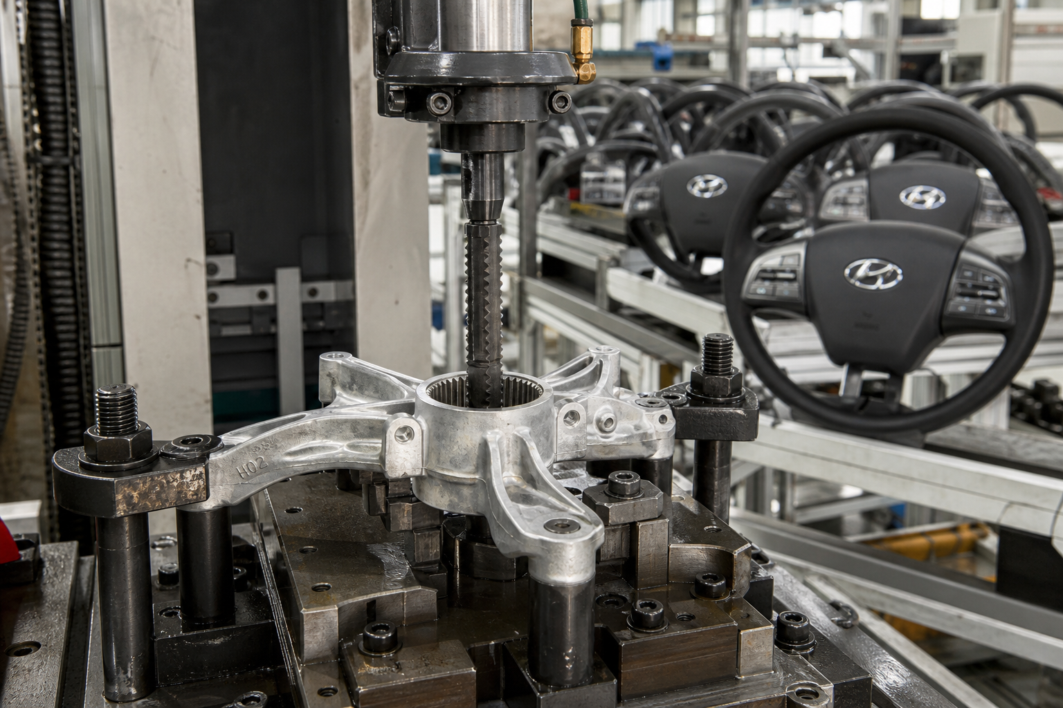
The mechanics are the standard internal broaching process covered in our spline broaching guide. The bore is produced first — drawn, punched or machined to a controlled diameter that also serves as the broach’s pilot. A pull-type spline broach is then drawn through the hub in a single stroke. Its cutting teeth rise progressively from the pilot diameter, each removing a share of the spline depth, until the finishing teeth generate the final tooth form, spacing and major diameter. The spline’s profile lives in the ground tool, not in machine motion, so every tub in the run receives the same form from the same tool — repeatability that comes from the tool itself, which is what a fast-paced assembly line wants downstream.
Why a Spline, and Why Broached
A spline distributes drive torque across many teeth instead of concentrating it on one key, which suits a hub that accelerates a load of wet laundry to spin speed and decelerates it thousands of times over its life. It also self-locates the tub concentric to the drive shaft — a round-the-circle symmetry a single keyway cannot offer without additional locating features. Broaching wins the feature because it finishes the form in one pass: no index-and-recut cycle, no second setup, and cycle content that fits inside the takt of a high-volume line. Slot milling or shaping the same form in a thin-wall hub would demand multiple passes, careful indexing and a tool engagement pattern far less friendly to a part that must not distort.
What the Part Demands of the Tooling
The hub region of a formed tub is not a machined blank. Its bore may carry forming history — slight ovality, weld-adjacent stock variation, material that has already work-hardened from drawing. The broach package must be designed against the real incoming condition: a pilot length that bridges the bore, tooth rise distributed to keep per-tooth force within what a thin hub section can carry, and finishing teeth that true the form rather than assume a round pilot. Where the design allows, the spline is positioned relative to machined datum features on the same setup, so the drive connection is concentric and square to what the assembly actually references.
Outer Trough Features: End Faces, Slots and Seats
The trough side of the family contributes surface work rather than bore work. A collecting trough carries sealing surfaces where it closes against adjacent structure, mounting features that position it in the cabinet, and port locations where water enters and drains. Among these, the features that repeat with a defined form are broaching candidates: locating notches that set the trough’s rotational position, slots that receive tabs or fasteners, and seat faces around ports where a seal or fitting bears. These are surface broaching operations — the tool travels across or around an accessible face, cutting the form in one pass.
Material reality widens the conversation. Troughs run in stainless steel, enamel-coated steel and engineering polymers, and the cut features appear in all three. The metal cases follow the same tooling logic as the tub work with somewhat stouter walls; the polymer cases are broachable too, with geometry and clearance ground for a material that shears rather than tears — the range of workable materials is covered on our what materials can be broached page. The constant across materials is the selection rule this site applies everywhere: broaching earns the feature when a formed profile or flat must repeat identically at volume, and stays off the part when a simpler process meets the tolerance.
Thin-Wall Workholding: Supporting the Part Instead of Distorting It
Everything in this family is thin-wall. A tub or trough section that is stiff enough to survive its service life is still flexible under a concentrated clamping or cutting load, and a fixture that would be unremarkable on a machined casting can ovalize these parts outright. The fixture design problem is therefore not “how do I hold this” but “how do I hold this without changing its shape” — a problem with established answers, treated in depth in our broaching fixture design guide.
Three tactics carry the load. First, support the form: a support mandrel or form-backed nest under the hub or flange region places solid backup directly beneath the cutting zone, so broaching force flows into support structure instead of into wall bending. Second, distribute the clamp: segmented or full-circumference clamping that mirrors the part’s own shape, with clamp force spread over broad pads, instead of a few point contacts that dimple a wall. Third, aim the forces: the cutting force vector should press the part into its support, and clamping should be axial against a true seating surface rather than radial squeeze wherever the design allows. Locating surfaces are machined features, not as-formed surfaces, so the part seats repeatably part after part.
The payoff is measured downstream. A hub broached under poor support produces a spline that is form-correct at the cutter but position-distorted on the part — and a tub that vibrates at spin speed. For this family, the fixture is half the process, and it is quoted with the machine, not after it.
Stainless and Enamel Steels: Cutting Practice That Matters
The dominant metals in this family are austenitic stainless steels and enamel-grade steels, and both bring the behavior that defines broaching practice on difficult materials: work hardening. Austenitic stainless strengthens markedly under cutting deformation — a tooth that rubs instead of cuts, or a pass that dwells on the surface, leaves a hardened skin that the next tooth must penetrate, accelerating wear and degrading form. The discipline is straightforward and qualitative: keep edges sharp and replace them on schedule rather than on failure; ensure every tooth takes a real chip with positive geometry suited to the material; maintain flood coolant to clear chips and heat from the hub; and set rise-per-tooth high enough to cut beneath any previously hardened layer. These are the standard practices for broaching the gummy, hardening grades discussed on our materials page.
Enamel steel adds a process-sequence consideration rather than a cutting one. Porcelain enamel fires at high temperature and a thin-wall formed part moves in the kiln — so where a machined feature and an enamel finish coexist, the firing-versus-cutting sequence is a design decision with dimensional consequences. The broaching itself sees only the base steel, but the tolerance scheme must respect whichever sequence the design chooses. Welds are the other local reality: a feature cut near a seam works material that has seen thermal cycles, and tooth loading there is set accordingly.
Machines for the Application: Two Dedicated Platforms
Because the two feature families are geometric opposites — internal form versus surface form — they are served by two machine configurations. Internal spline and keyway work on the tub hub is pull-type internal broaching: a vertical or horizontal machine with stroke matched to the broach length and hub depth, a pull mechanism sized to the total cutting force of the spline, and workholding built around the support-mandrel logic above. That configuration is the basis of our inner tank broaching machine — a dedicated platform for the hub drive features of formed tubs at production volumes, engineered around the part’s thin-wall reality rather than adapted to it.
Surface work on troughs — notches, slots and seat faces — is the province of surface broaching: shorter stroke, higher force per pass, tooling ganged to cut multiple features in one travel. Our outer trough broaching machine carries that configuration for the trough and tank side of the family. Both machines share the family traits of dedicated broaching equipment: the full feature set is programmed into the tool, the machine’s job is to deliver stroke, force and repeatability, and changeover between part variants is a tooling and fixture change rather than a reprogramming exercise. They sit within the wider broaching machines range, which covers the general work that surrounds this family in an appliance plant — shafts, brackets and die-cast components on the same lines.
Takt, Automation and Line Integration
Appliance plants are takt-driven: the line moves at the pace of final assembly, and every upstream operation must fit inside it or buffer against it. Broaching fits well on cycle content — one stroke finishes the feature, so the cycle is stroke plus return plus load, with no multi-pass accumulation — but the integration questions are broader than cycle time. Load and unload must match the line’s material flow, whether manual with poka-yoke locating or automated with gantry or robot handling. In-machine sensing — broach force monitoring, breakage detection, end-position confirmation — protects both the tool and the takt, because an undetected damaged broach passes bad splines at line rate until someone stops it.
Tool management is the other integration reality. A spline broach is a high-value, part-specific asset with a finite sharpening life, and production planning treats it as a line-side critical item: scheduled regrinds, dimensional tracking of the worn tool against the spline’s tolerance band, and spare tooling on hand so a regrind never stops the line. Chip and coolant handling, guarding and changeover ergonomics round out the picture.
Related Broaching Cases on This Site
This case belongs to a series, and the neighbors are instructive. The closest in format is cylinder block broaching — the archetypal volume-production case where the same question is asked of a cast iron part: which features go to broaching, which to boring and milling, and why the answer holds at millions of units. The connecting rod and bearing cover cases extend that casting-and-forging family through the joint-face and bore-interface questions. What the appliance cases add to the series is a different blank condition — thin, formed, welded sheet instead of rigid cast metal — and therefore a different center of gravity: the fixture carries as much of the process burden as the tool. The spline broaching guide remains the technical deep-dive behind the flagship application described here.
Frequently Asked Questions
Can the washing machine inner tub itself be broached?
No — and no cutting process wants that job. The tub body is a sheet metal product: deep drawn, rolled, welded and perforated in a stamping-type process sequence. Broaching’s scope on an inner tub is the machined features the drive system depends on — the internal spline or keyway in the hub bore, and end-face details such as locating slots and notches. That division of labor is the honest boundary of the application, and it is where the volumes and the economics of broaching genuinely live.
Why broach the spline bore instead of milling or shaping it?
Because the feature is internal, formed, and repeated at very high volume — the exact conditions that favor broaching. A pull-type spline broach generates the complete tooth form, spacing and diameter in one pass, with the geometry held in the ground tool rather than built up from indexed cuts. Milling or shaping the same internal form requires multiple passes and indexing, takes longer per part, and applies a less favorable load pattern to a thin-wall hub. At appliance volumes, the one-pass economics and tool-defined repeatability are decisive.
How do you keep a thin-wall tub from distorting during broaching?
With fixture engineering, not lighter cutting. The standard architecture: a support mandrel or form nest backing the hub and flange region directly under the cutting zone; clamping distributed over broad, segmented pads that mirror the part’s shape instead of point-loading it; axial clamping against machined locating surfaces in preference to radial squeeze; and cutting force directed into the support rather than across unsupported wall. Tooling contributes by keeping per-tooth rise low enough that total cutting force stays within what the supported section can carry.
Are polymer troughs and tanks broachable too?
Yes, engineering polymers are within the process’s range — broaching cuts a clean formed feature in thermoplastics when the tool geometry, clearances and edge preparation are ground for the material rather than carried over from steel practice. The metal side of the family remains the core application: stainless and enamel steels carry the drive and sealing features with the tightest tolerance stakes.
If your production line carries formed inner tanks or troughs with machined drive or end-face features — spline bores, keyways, locating slots, seat faces — that is the work these platforms are built for. Send the part drawing, material specification and annual volume, and our engineering team will return a machine, tooling and fixture proposal with stroke, force and cycle worked out against your part. Start on the inner tank broaching machine page or the outer trough broaching machine page, or contact us directly with your workpiece details.