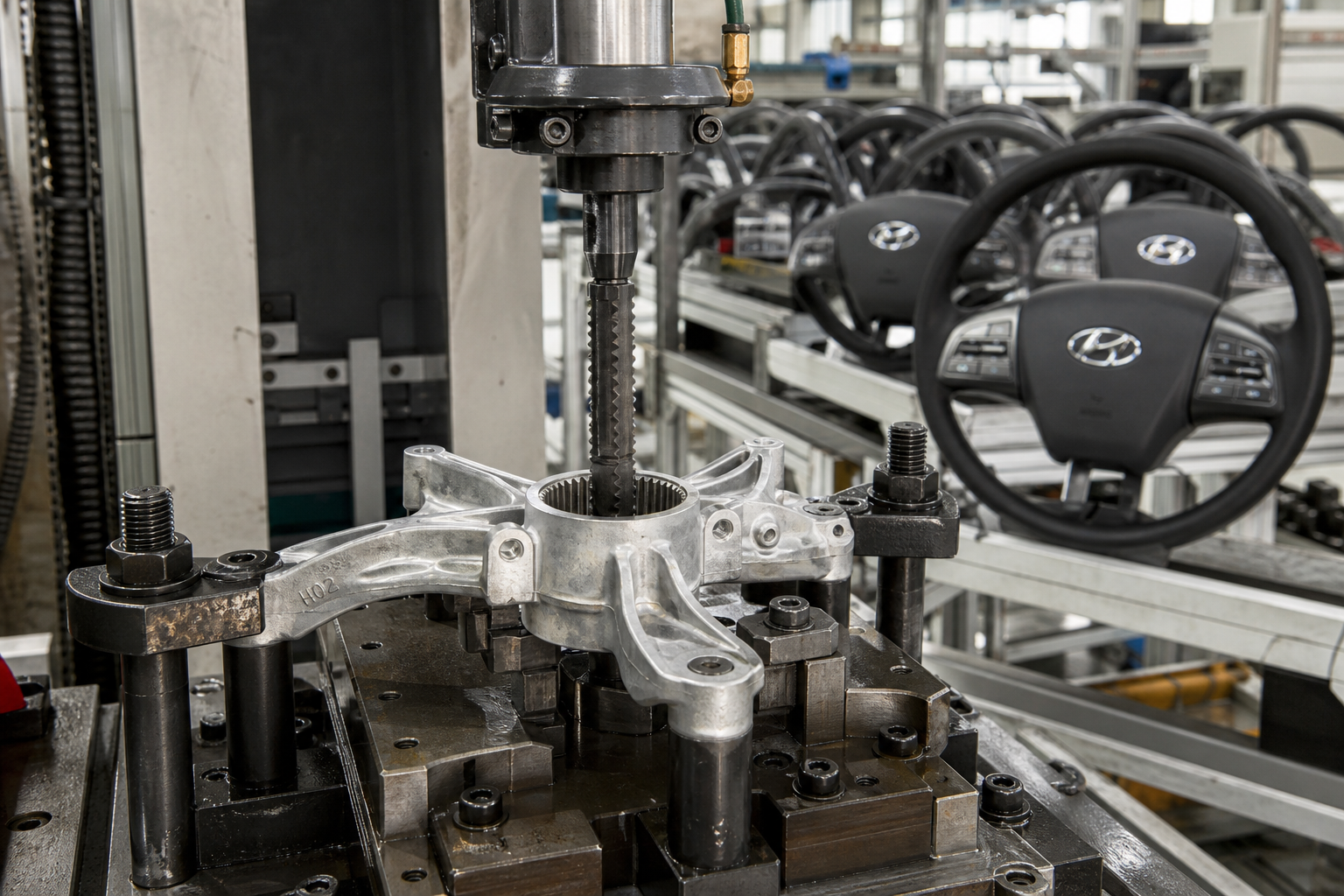
An involute spline is a splined connection whose flank surfaces are involute curves — the same geometry that defines an involute gear tooth. When that profile is cut on the inside of a bore with a broach, one stroke of a ground tool produces a complete internal spline: every tooth, every flank, every fillet, finished simultaneously and repeated identically on every part that follows. Involute spline broaching is the productivity engine behind the internal splines in transmission gears, steering columns, power-take-off components and a long list of aerospace hardware.
This article is the involute-specific companion to our spline broaching complete guide. The general process — tooth rise, chip load, machine selection, troubleshooting — lives there. Here we stay on what makes the involute form special: the geometry, the standards, the three centering methods and what each demands of the broach, the tooling itself, and how the finished spline is inspected.
What Is an Involute Spline?
A spline is a mechanical connection that transmits torque between a shaft and a hub through multiple teeth machined around a circle. An involute spline is one whose tooth flanks are involute of a circle: the curve traced by unwinding a string from a base circle. Each tooth is described by the same parameters as an involute gear — number of teeth, module or diametral pitch, pressure angle, and tooth thickness — and by extension inherits the gear tooth’s defining property: rolling contact between mating flanks rather than sliding wedging between flat faces.
The pressure angle is measured at a defined reference diameter, and because the involute’s slope changes continuously along the flank, the local pressure angle varies from root to tip. Only one involute exists per base circle, so a flank that deviates from its theoretical curve is a different curve, not a softer tolerance — and it shows up in the fit. That is why involute splines are specified by parameters, and why the tools that make them are judged by how faithfully they hold the generated curve.
Why the Involute Profile Dominates Modern Splined Connections
Manufacturing consistency. The involute is the profile that generating processes produce naturally. Hobbing, shaping, grinding and form-grinding all create involute flanks from the rolling kinematics of the cutter — one rack-profile cutter family covers an entire range of tooth counts. For broaching, the same logic applies in reverse: the broach’s flanks are ground as the exact negative of the involute, and once ground, every stroke reproduces that master curve in the workpiece.
Self-centering under load. Because flank contact occurs along curved surfaces at a pressure angle, torque load produces a radial force component that pulls the mating members into concentric alignment. A side-fit involute spline with many teeth sharing load centers itself, while flat-flank connections rely on a controlled diameter to achieve concentricity. This is the property that lets involute splines carry torque with generous per-tooth clearance yet still run concentric — a combination straight-sided designs struggle to match.
Interchangeability. Standardized modules, pressure angles and tooth-thickness tolerance bands mean an internal spline cut to a standard specification accepts any mating external spline cut to the same specification and class. The high tooth count also spreads torque across many contact areas, reducing unit pressure and fatigue sensitivity. The result is the profile of choice across automotive transmission components — see our transmission gear internal spline broaching application article — as well as steering columns, PTO driveline parts and aerospace actuator components.
Involute vs. Straight-Sided Splines at a Glance
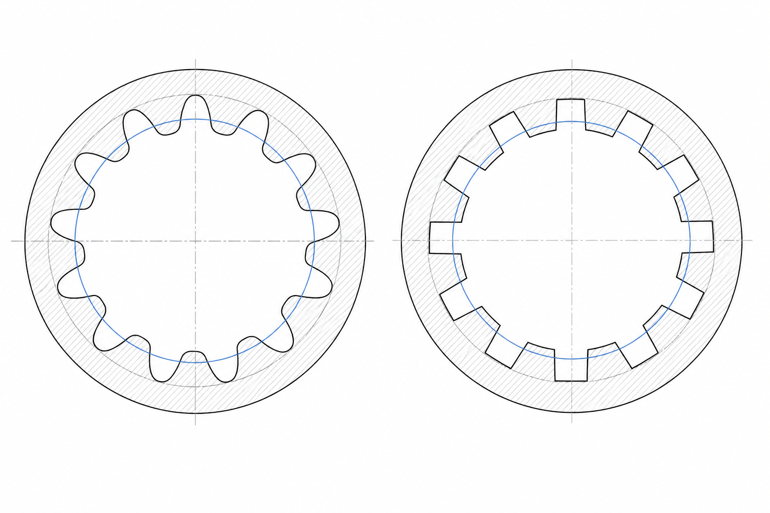
The older spline architecture is the straight-sided or parallel-sided form: teeth whose flanks are flat planes radial to the axis, as in rectangular splines. Both families are broached successfully every day. The table below condenses the engineering comparison.
| البُعد | Involute Spline | Straight-Sided Spline |
|---|---|---|
| Tooth profile | Involute curve, fully defined by base circle, pressure angle and tooth thickness | Flat radial flanks; profile defined by tooth width and spline dimensions |
| Load behavior | Curved flanks share load across many teeth and self-center under torque | Flat flanks contact on planes; concentricity depends more on a controlled diameter |
| Centering options | Side fit (default), major diameter fit, or minor diameter fit | Typically major or minor diameter centered; side control is secondary |
| Governing standards | ANSI B92.1 (inch); ISO 4156 / DIN 5480 (module-based metric) | Various national rectangular-spline standards; legacy drawings common |
| Broach grinding | Flanks must be form-ground to the true involute; profile accuracy is the core requirement | Simpler flank geometry; grinding is more straightforward, inspection less curve-dependent |
| Tool cost drivers | Involute form grinding, correction geometry and tolerance class of the finished hole | Primarily size, number of teeth and length of cut |
| Typical preference | New designs, automotive and aerospace torque paths, standardized mating | Repairs of legacy components, some PTO and equipment shafts built to older drawings |
Two rows deserve emphasis. Centering options: the involute form supports side-fit assemblies that straight-sided splines cannot, because the curved flank is what makes side contact self-centering. Broach grinding: a straight-sided broach flank is a plane, but an involute broach flank is a mathematically exact curve — the broach is, functionally, a ground negative master gear, which is the source of both its precision and its cost.
The Standards Landscape: ANSI B92.1 and the ISO/DIN Module System
Two standard families define the involute splines that broaching machines cut. In inch-unit markets, ANSI B92.1 is the reference. It specifies involute splines by diametral pitch and number of teeth, with a pressure-angle family — 30 degrees as the workhorse, alongside 37.5 and 45 degree series for specific applications. B92.1 distinguishes flat-root and fillet-root tooth forms for the 30-degree series, defines tooth-thickness tolerance classes, and standardizes the fit concepts — side fit and major diameter fit.
In metric markets, ISO 4156 and DIN 5480 govern, both built on the module system familiar from gearing: basic rack profile, module, number of teeth, pressure angle and reference diameters, with tolerance and deviation systems that place the actual tooth thickness inside a defined band. DIN 5480’s naming system encodes the nominal dimensions directly, so a broach maker translates the drawing callout straight into grinding data.
For the broaching engineer, three practical consequences follow. First, the standard named on the drawing fixes the geometry vocabulary: module versus diametral pitch must never be mixed, and the pressure-angle series changes fillet and tool-tip geometry. Second, the tolerance class selected by the designer sets how tightly the broach’s finishing teeth must hold effective tooth thickness, which drives the number of finishing teeth and the regrind budget. Third, the inspection method — pin or ball measurement — is standardized along with the geometry, so the broach and the gage are ordered against the same callout.
Centering: Side Fit, Major Diameter Fit, Minor Diameter Fit
Concentricity between mating members has to come from somewhere, and the three classical answers each change the broach.
Side Fit
In a side-fit spline, concentricity is governed by flank contact itself: the mating tooth thicknesses are sized so that torque loads the flanks and the involute geometry centers the hub on the shaft. The major and minor diameters are deliberately given clearance and are not controlling dimensions. For the broach, this is the most forgiving arrangement: the tool’s tip may carry a generous radius instead of a sharp corner, tooth thickness is the dimension the finishing teeth must hold, and the bore’s major diameter floats within a wide band. Most production involute splines are side fit for exactly this reason: the broach controls the one dimension that matters and is indifferent to the ones that do not.
Major Diameter Fit
Here the internal spline’s major diameter — the circle over the bottoms of its tooth spaces — mates with a ground external major diameter and controls concentricity. Flanks still carry the torque, but radial location comes from the diameter pair, so the internal major diameter becomes a tightly held dimension. That lands directly on the broach: the tool’s tooth tips must be ground to the major-diameter tolerance and hold it over the whole regrind life. Tooth-tip corners are controlled rather than generously radiused, and the finishing section of the broach is ground with the major diameter treated as a gauge dimension. Major-diameter-fit broaches cost more and live shorter regrind lives than equivalent side-fit tools.
Minor Diameter Fit
In a minor-diameter-fit connection, the internal spline’s minor diameter — the tip circle of the internal teeth, which in a broached part is the prepared bore ahead of the spline teeth — mates with a precisely ground external root diameter. The consequence for broaching is architectural: the minor diameter is not cut by the spline teeth at all; it is the pilot hole, produced by drilling, boring or reaming before the broach ever enters. The broach must respect that existing bore — its pilot and tooth roots must clear it without enlarging it — and concentricity is inherited from the preparatory operation rather than from the broach. This arrangement puts a premium on the quality of the pre-spline hole and on fixturing that locates from it — hence its association with closely controlled aerospace and precision assemblies.
Inside the Involute Spline Broach
Structure and Tooth Progression
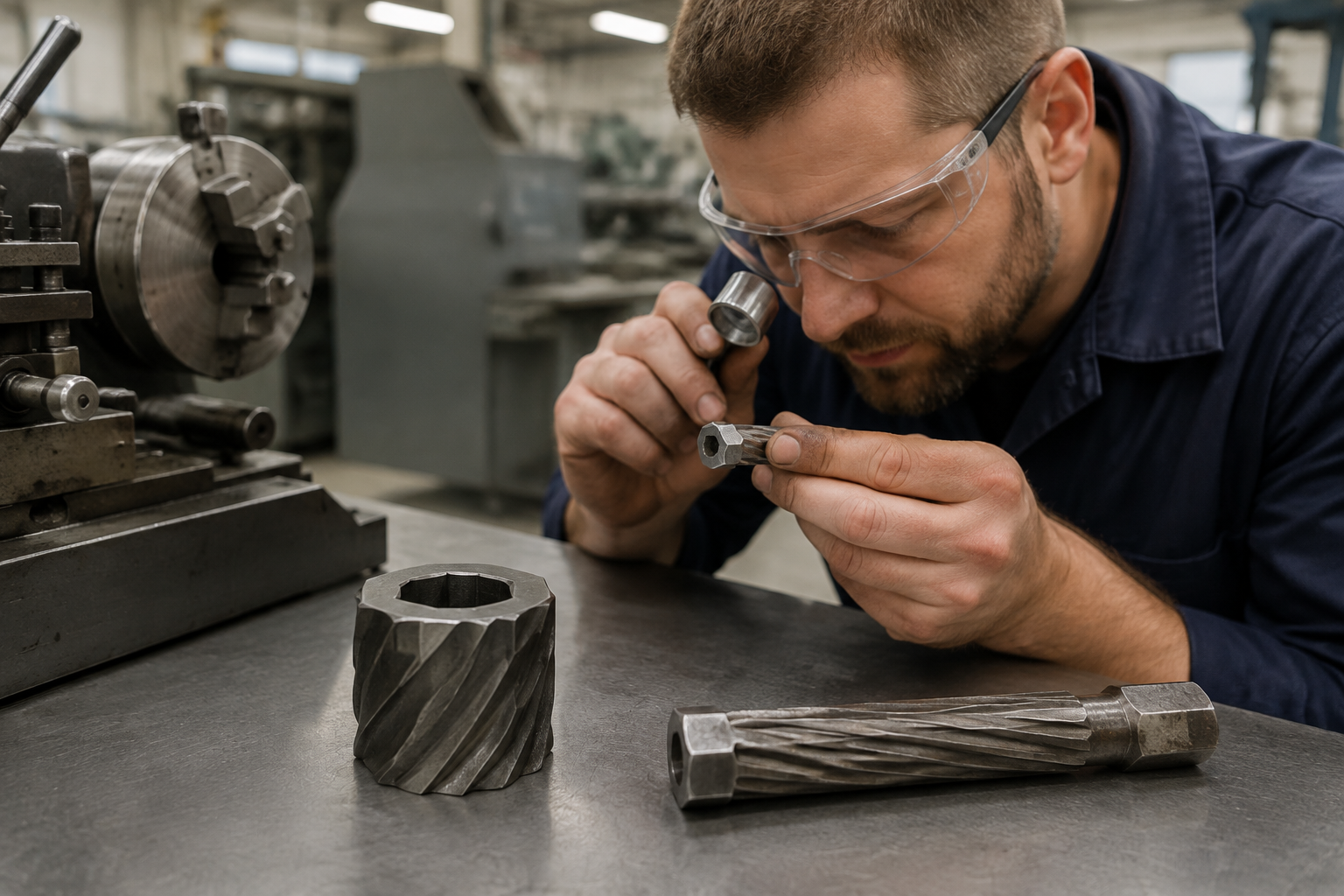
An internal involute spline broach follows the classical architecture — roughing teeth that remove the bulk of the material, semi-finishing teeth that converge on the flank form, and finishing plus sizing teeth that bring tooth thickness and profile to size. The distinguishing feature is that every tooth from first to last carries the full involute form, so the tool is engaged in flank generation from the moment it enters the bore. Tooth rise is distributed so that each cutting edge peels a controlled layer; toward the finish section the rise drops to fractions of the roughing value so the last flanks are generated by light, stable cuts. The general design logic — pitch, chip space, rise-per-tooth trade-offs — is covered in our article on how broaches are designed; what follows here is peculiar to the involute.
Profile Grinding and Corrections
The flanks of an involute broach are form-ground on machines that dress the wheel to the involute curve, and the finished tool is inspected as a gear would be — flank profile deviation is a specified quantity, not a byproduct. Beyond the pure curve, production broaches carry deliberate corrections: tip radius and root fillet geometry to clear the mating part and to strengthen the tooth root, tip and flank relief at the corners of the leading teeth to protect the form during roughing, and surface finish on the flanks fine enough to print cleanly into the bore wall. Broach-to-broach consistency matters as much as absolute accuracy: production scheduling assumes any reground successor still cuts parts inside the same tooth-thickness band.
Tolerance Class and Regrind Behavior
Involute broaches are built to the tolerance class of the spline they will cut: the finishing teeth hold tooth thickness inside a band derived from the drawing’s class, and the length of the finishing-and-sizing section is sized so the tool can be sharpened repeatedly while still delivering parts in band. Sharpening regrinds the rake faces; because the involute flanks are the generating surfaces and the cutting edges advance along them, the ground profile is preserved through the regrind — the property that makes a spline broach a long-lived master tool. The regrind budget ends when the finishing section shortens below what the class requires; the tool is then rebuilt or replaced. Our involute spline broaches page describes the tooling program in detail.
Cutting Strategy: What Changes When the Form Is Involute
The full internal spline broaching workflow — hole preparation, pull versus push configurations, speeds, coolant and cycle timing — is laid out in the spline broaching complete guide and applies unchanged. Three strategy elements deserve involute-specific attention.
Chip formation on curved flanks. An involute broach tooth does not plane a flat surface; it peels a chip whose width and thickness vary along the curved edge as the tooth engages the flank. The chip gullets are accordingly sized for the flank chips the form actually produces, not for an equivalent-width flat slot. Coolant delivery matters correspondingly: the chips curl into the tooth spaces and must be flushed clear stroke after stroke, or packed chips print onto the finish flanks.
Prepared-hole discipline. The bore ahead of the broach sets the spline’s minor diameter and, with it, the tool’s pilot condition. The hole must be on size, round and straight before broaching — an oversize or bell-mouthed pre-hole lets the tool wander before full engagement and shows up as profile error at both ends of the cut. For minor-diameter-fit splines this discipline is the process; for side-fit splines it is cheap insurance.
Single-stroke versus broach sets. Short involute splines in ductile materials are routinely completed in one stroke of one broach — the economic heart of the process. Longer bores, harder materials or tighter classes are split into a sequence of broaches, each taking a share of the flank stock, with the final tool carrying the class-critical finishing teeth. The decision is volume-driven: at automotive rates, a broach set on an indexable machine still cycles in seconds, which is why involute spline broaching on dedicated broaching machines remains the benchmark cycle time for internal splines.
Inspecting the Broached Involute Spline
Inspection of involute splines mirrors gear inspection, with one divide that matters in production: functional verification versus analytical measurement — a distinction developed at length in our internal spline inspection article. On the functional side, a composite spline gage — a go/no-go master of the mating form — verifies in seconds that the part will assemble and transmit torque. On the analytical side, measurement over pins or wires (for external splines) and measurement between pins (for internal splines) converts tooth thickness into a single readable linear dimension: pins of a standardized diameter are seated in diametrically opposed tooth spaces and the resulting dimension compared against the calculated value for nominal tooth thickness.
Pin measurement is the natural partner of broaching because it speaks the same language as the tool: an out-of-band between-pin dimension on an internal spline points to tooth thickness, which points back to broach wear or regrind state, long before assembly problems appear. When the full picture is needed — actual flank profile deviation, index accumulated error, lead over the spline length — gear measurement instruments and CMMs with spline routines quantify the curve itself against its mathematical definition. Disciplined shops layer the three: gages at the machine, pin checks at intervals, analytical audits periodically.
Involute Broaching and Power Skiving: The Division of Labor
Power skiving has emerged as the leading alternative for internal gear teeth and overlaps with broaching on internal involute forms. The working division of labor is straightforward: broaching owns the blind-fast case — a through-bore, a stable design, high volumes, cycle times in seconds and profile fidelity from a ground master tool — while skiving earns its place where the feature is a blind pocket, where spline cutting must share a multi-task CNC cycle with other operations, or where designs change faster than dedicated tooling can amortize. The full comparison is treated in our article on broaching versus power skiving for internal gears.
Frequently Asked Questions
What is the difference between an involute spline and a straight-sided spline?
The flank geometry. An involute spline’s tooth flanks are involute curves — identical in mathematics to gear teeth — so the connection benefits from rolling flank contact, load sharing across many teeth and self-centering under torque. A straight-sided (parallel-sided) spline has flat radial flanks, a simpler form to grind and inspect, but one that centers on a controlled diameter rather than on flank contact. Both are broached routinely; new torque-transmitting designs overwhelmingly specify involute profiles, while straight-sided forms persist in legacy drawings and equipment repairs.
Which standards govern involute splines?
Inch-unit designs reference ANSI B92.1, which specifies splines by diametral pitch with a pressure-angle family (30 degrees as the common case, alongside 37.5 and 45 degree series), flat-root and fillet-root forms, and tooth-thickness tolerance classes. Metric designs reference ISO 4156 and DIN 5480, which are module-based systems built around a basic rack profile with standardized tolerance bands. The standard named on the drawing determines the broach’s grinding data and the inspection pin diameters, so it should be identified before tooling is quoted.
How do side, major-diameter and minor-diameter fits change the broach?
They change which dimensions the broach must hold precisely. Side fit concentrates the tool’s obligation on tooth thickness — the flanks control location — so the tooth tips can carry a generous radius and the tool enjoys the longest regrind life. Major-diameter fit adds a tightly held internal major diameter, which must be ground into the broach’s tooth tips and maintained through sharpening, raising tool cost and shortening regrind budget. Minor-diameter fit removes that diameter from the broach entirely: the minor diameter is the pre-broached hole, so concentricity is inherited from hole preparation and the broach must respect, not generate, that surface.
What tolerances can broached involute splines hold?
Broached involute splines are held to the tolerance class specified on the drawing, and the broach is manufactured to deliver that class over its regrind life. The controlling habits are: order the broach to the drawing’s standard and class rather than to a generic size; keep the prepared bore on size before broaching; track between-pin or over-pin measurements as the tool wears so regrinding is scheduled by data; and verify with composite gages on the floor, reserving full analytical profile measurement for tool qualification and periodic audits.
If your parts carry internal involute splines — transmission gears, steering components, PTO hubs, actuator housings — the fastest route to a cycle time is a drawing-led review: send the spline specification with its standard, class and fit, the material and the annual volume. Our engineering team returns the broach design, the machine configuration and the inspection plan as one package. Start with the involute spline broaches tooling page and the broaching machines overview, or contact us directly with the workpiece drawing.