Every rotating shaft in a machine runs in a bore — and wherever that bore is built from two pieces, the closing half is a cap. Main bearing caps close the crankshaft bores of an engine block. Connecting rod caps close the big-end bores around the crank pins. Housing and end covers close the bearing bores of gearboxes, motors and axles. A cap looks like the simplest part in the family: a block of metal with a half-bore and a pair of bolt holes. Its machining decides the precision of the whole assembly, because the cap never carries that precision alone — it carries it with the body it bolts to.
Bores appear in this article’s title, but they are not broached — that boundary comes first and stays firm. A bearing bore is finished by boring and honing, usually after assembly, so the completed bore is round and co-axial as a bolted-together system. What broaching owns on caps and covers is everything around the bore: the split face where cap meets body, the locating serrations, steps and grooves that position the cap laterally, defined-width pad and seat faces, and certain internal groove features on cover parts. These are flat, formed, repeating features cut at automotive volumes — the reason cap lines have carried broaching stations for as long as engine plants have existed.
This article walks the family in order: what main bearing caps, rod caps and general covers each are, which of their features are realistic broaching candidates, and how the split face is machined for flatness and interchangeability. From there it covers locating features, pairing strategies, the three material families, and line integration at takt. It is the cap-side companion to our cylinder block broaching case — the body-side half of the same joint — and to connecting rod broaching, the fatigue-critical member of the family.
The Bearing Cap and Cover Family: One Name, Several Parts
Main Bearing Caps: Closing the Crank Bores
An engine block carries a row of half-bores along its skirt — one per main bearing — and each is closed by a bolted-on cap to form the complete crankshaft journal bore. A passenger-car inline engine therefore consumes a row of identical caps per block, cast in sets, machined in sets, assembled in sequence. The cap is a structural member, not just a cover: it clamps the crankshaft against firing loads, resists separation and lateral shift, and its joint faces are among the most heavily loaded machined surfaces in the engine. Material follows the block — gray iron caps on iron blocks, and on many aluminum blocks a harder iron grade, because bearing performance depends on it. Design variants matter: some engines use individual caps, others a one-piece bedplate closing all the bores at once, which changes part size but not the feature logic.
Rod Caps: The Fatigue-Critical Sibling
The connecting rod big-end cap is the same idea at smaller scale and far higher stress. The rod is forged steel in most high-volume designs, and the joint is where two philosophies divide. Fracture splitting — cracking the rod from the cap along a pre-weakened plane — has replaced machined joints on a large share of passenger-car programs, because a fractured surface re-mates in exactly one position with no locating features at all. But the machined joint survives wherever splitting does not apply: heavier-duty rods, joints that must open for service, and materials that will not crack cleanly. A machined rod joint carries a flat split face plus a positive locator — tongue-and-groove, stepped face or serration set — and producing those forms on both halves is classic precision broaching work, developed in the connecting rod case linked above.
General Covers and Housing Caps
Beyond the engine, the family widens into covers and caps that close bearing bores in gearboxes, reducers, electric motors and axles. These parts are frequently die-cast aluminum, larger and thinner than engine caps, and their machined features cluster around two duties: a joint face that seals against the housing — sometimes carrying a gasket or sealant groove — and internal features such as defined grooves or recesses near the bore. Broaching appears in both roles here: surface broaching for joint faces and shaped recesses at volume, internal broaching for groove forms where lot sizes justify it. The candidates framework applies unchanged — many cover faces are milled perfectly well, and broaching earns the feature only when form complexity or volume repetition pays for the tool.
What Broaching Actually Does on Bearing Caps
Across the family, the features that realistically fall to broaching share one shape: flat or profiled surfaces, repeating identically, at production volumes. Framed as candidates — because every design distributes work differently:
- Split faces. The cap-to-body joint face, where flatness, texture consistency and control of the joint plane decide how the assembled bore behaves.
- Locating serrations, steps and tongue-and-groove forms. Positive lateral location on the joint, cut to profile in one pass with the face itself.
- Bolt seat faces and defined pads. Square, flat seating for the cap bolts, and width-controlled pads referencing other assemblies.
- Cover joint faces and sealant grooves. Flat sealing faces on housings and end covers, with formed groove profiles where the design calls for them.
- Internal groove features. On cover-type parts, defined grooves and recesses produced by internal broaching where volumes justify a dedicated tool.
The exclusions are just as definite. The bearing bore is never broached — it is bored and honed, almost always after the cap is assembled, and on block families the whole bearing line is line-bored in one setup so the bores are co-axial as a system; the body-side half of that logic is in the cylinder block case. Bolt holes are drilled, threads tapped. A sourcing engineer reading a “bearing cap broaching” scope should read it as joint faces and formed local features on caps and covers — the honest division of labor that comes first in every scoping conversation.
Split Face Broaching: Flatness and Interchangeability
The split face is the cap’s defining machined surface, and its requirements read short but cut deep. It must be flat, so the cap seats without rocking under bolt preload. It must sit at a controlled distance from the half-bore centerline — the cap height — because cap height plus body height sets the assembled bore’s size and roundness before final boring. And across a run it must be consistent part to part, because the line’s ability to assemble any cap with any body — or repair assemblies years later — rests on that consistency. Interchangeability is a manufacturing property, not a drawing note, and it is manufactured on the joint faces.
This is where broaching’s structural advantage lands. A milled face inherits variation from cutter wear, insert changes and pass-to-pass paths; a broached face inherits its geometry from the tool, and the tool changes slowly and on a schedule. Roughing teeth strip the cast skin, finishing teeth generate the final plane, and every cap in the run receives the same surface from the same cutting lands. For a row of identical caps at engine volumes, that converts into a tight cap-height distribution: assembled bores present a uniform correction to the line-boring station instead of a scatter the finishing pass must chase.
The economics follow the same logic as deck-face work on blocks, at cap scale. The tool is expensive and long-lived; the part is small and repeated thousands of times per day. Staged in multi-part fixtures — a full row of caps per stroke, or caps fixtured alongside their bodies — the broach finishes the whole set with one pull. Milling keeps the feature on low-volume programs; broaching takes it when run length and interchangeability requirements are both real.
Locating Serrations, Steps and Grooves on the Joint
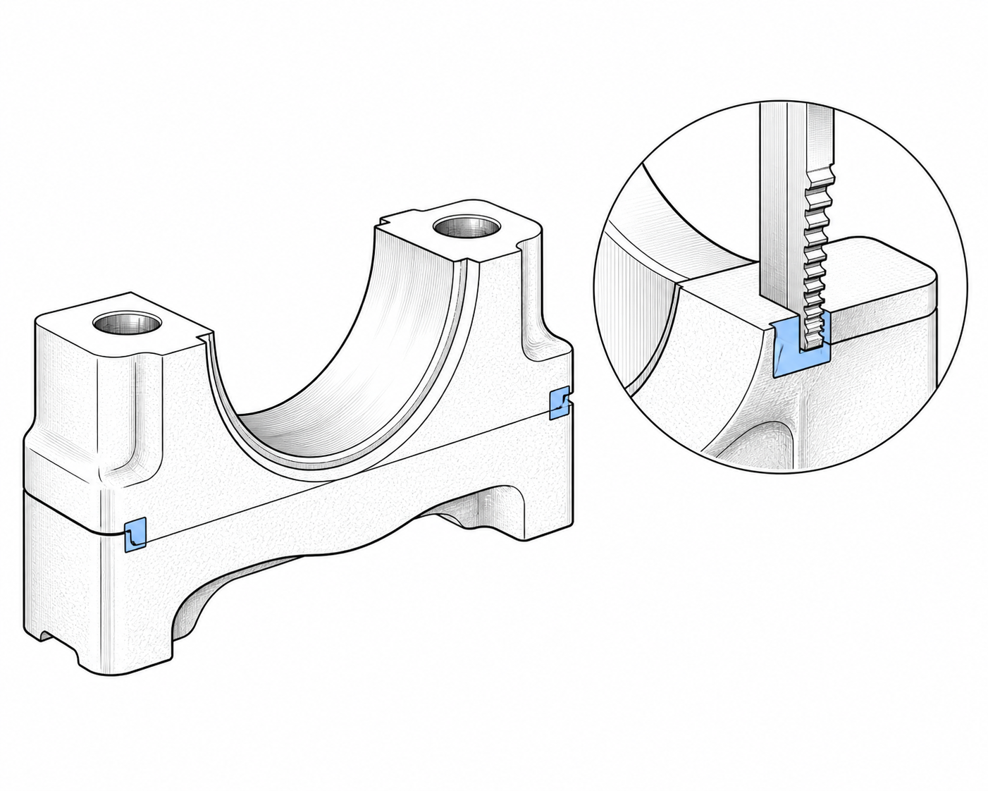
Many capped joints carry more than a flat face. To hold the cap against lateral shift under load — and to position it before the bolts develop full clamp — the joint carries a positive locator: serrated tooth forms along the split line, a stepped face, or a tongue-and-groove pair. The teeth engage as the cap seats, position it laterally, and take shear loads that would otherwise migrate into the bolts. On machined-joint rods these locators are functionally mandatory; on main bearing caps they are common; on industrial housings they appear wherever body-to-cover alignment must survive service loads.
These forms are a showcase for broaching because the geometry is designed into the tool once and then repeats forever. Tooth profile, pitch, flank angles, depth and the form’s relationship to the reference surface are ground into the broach — and a surface broach can generate the split face and the locating form in the same stroke, so the form sits at a fixed relationship to the face by construction. The critical question is matching across the joint: body-side and cap-side forms must engage. When both halves are broached from tools built as a designed pair, engagement is controlled through the tool set rather than downstream fitting.
Groove features extend the same logic. Sealant and gasket grooves on cover joints, oil grooves opening at the split line, and positioning slots for pins or keys are single-profile, repeating forms — one more set of teeth on a broach already cutting the face. The deciding inputs are form complexity and volume: if the groove can be carried on the tool, broaching produces it more consistently than a second setup.
Cap-to-Housing Strategies: Interchangeability, Labeling and Bore Finishing
How caps and bodies are machined relative to each other is a strategy decision that precedes machine selection, and three patterns cover most of industry. Which one a program uses is design- and volume-specific — the broaching input is similar in all three.
Fully interchangeable. Both halves are finish-machined to their own tolerances, any cap may be assembled with any body, and the assembled bore is then line-bored or bored-and-honed to final size as a system. This is the high-volume automotive pattern, because pairing logistics would strangle the takt. Interchangeability is bought upstream: tight distributions on split faces and cap heights — precisely what a broached joint delivers. The finishing pass then removes a small, uniform correction from every assembly, the condition its tooling life and bore quality depend on.
Labeled and paired. Caps and bodies are machined as matched couples, identified by marking — dot peen, laser code or pin stamping — tracked through assembly, and finished together. Pairing trades logistics complexity for looser interchangeability demands on the halves, and appears where volumes are lower, parts large, or the bore must be finished without an interchangeability budget: big-bore industrial engines and heavy drive units are the natural territory. Broaching remains relevant here too — even a paired cap wants a flat, consistent split face and accurate locating forms; pairing relaxes the height distribution requirement, not the joint geometry.
Fracture split. The rod-family third way: no machined joint at all, the crack being its own locator. It removes split-face and locator broaching entirely — which is why machined-joint broaching survives next to it, on every rod that cannot or should not crack. The comparison between the two routes is covered in the connecting rod case.
Cast Iron, Forged Steel or Aluminum: Material Consequences
The cap family spans the three material worlds that dominate broached automotive parts, and the broach changes character across them.
Cast iron caps — gray iron on most main caps and housing covers — bring the casting realities: a skin with scale and local hard spots, abrasive discontinuous swarf, modest speeds. The tool answers with tough roughing geometry and rise-per-teeth deep enough to cut beneath the skin, honed carbide teeth, and pitch set so casting porosity never leaves too few teeth in cut. The cast-skin strategy is shared with the whole iron castings family — the brake caliper broaching case develops it in depth on the same logic.
Forged and spheroidal-graphite iron caps — rods, heavy-duty main caps — shift the problem from abrasion to toughness. The material shears in longer, continuous chips, forces run higher, and the broach needs chip-breaking gullet geometry, strong edge preparation, lower speeds with flood coolant. Form accuracy under load becomes the design driver: tooth forms on a rod-joint broach must hold their finishing relationship over higher forces, which is why joint-form broaches for steel are engineered, not catalogued.
Die-cast aluminum covers invert everything again: soft but abrasive matrix, silicon phase attacking edge sharpness, stringy chips demanding chip room and polished rake faces, PCD teeth on high-silicon grades — and cutting speeds several multiples of iron, converting directly into stroke time. On cover lines that margin often lets one station absorb several features and still fit the takt.
Takt Time and Automation: Multi-Part Fixtures and Quick Change
Caps are small parts consumed in sets, and that shapes their production engineering more than any feature does. The economics are multi-part by nature: a full set of main caps per engine, rod caps machined alongside their rods, covers paired with housings — so the fixture presents rows, not singles. A surface broaching stroke already longer than one cap costs little more to take five, and the marginal cycle time per cap collapses accordingly. The discipline is in the details: one shared datum scheme across every nest, clamping that closes the force loop through stiff material, chip evacuation sized for a full row per stroke — the disciplines our broaching fixture design guide is written around.
Against the line’s takt, cap stations use the standard automation levers: shuttle or dual-station fixtures that hide loading inside the cutting stroke, gantry or robot exchange tied to the line’s part logistics, and staging that groups cap and body features into one handling wherever the process plan allows. Tool management is engineered as part of the station: a rotating spare-broach strategy keeps reconditioning off-line, and the broach change itself is a quick-change operation measured in minutes.
Process control mirrors the family’s other broaching stations. Joint faces and locator forms are gauged features, so in-process or downstream measurement feeds SPC; and because every stroke generates a characteristic force signature, force monitoring doubles as an early-warning channel — a shift in the curve flags wear, a chipped tooth, or a casting anomaly before the gauge moves. On a row-per-stroke cap station, one pull covers many parts, making this one of the most efficient quality instruments on the line.
The Bearing Cover Broaching Machine
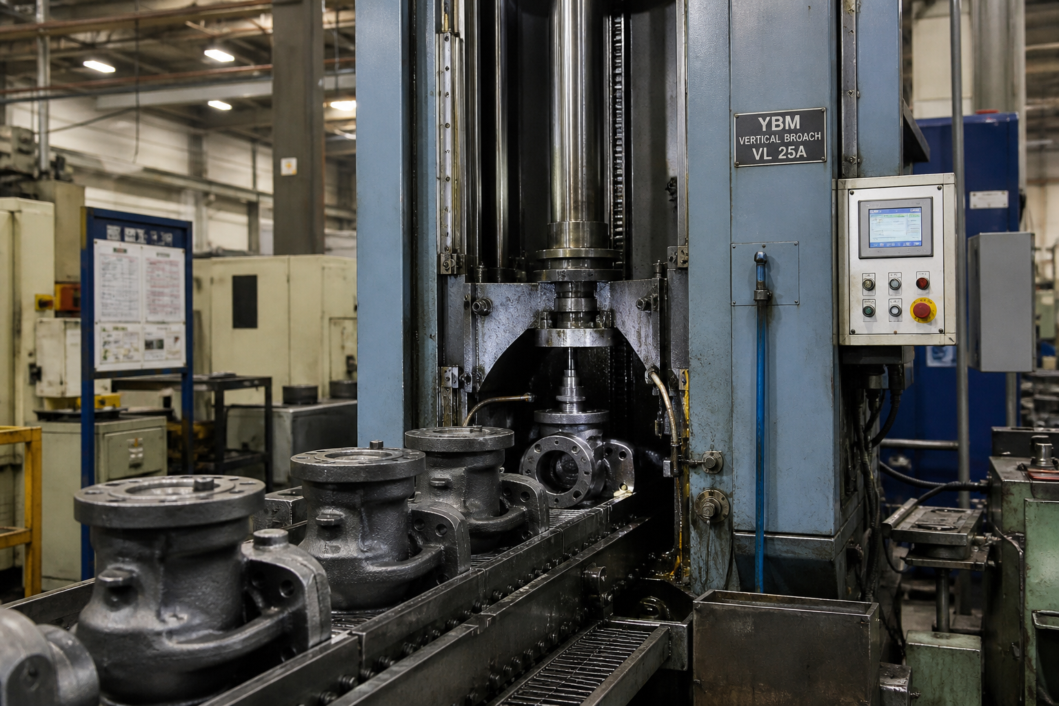
When the feature list and volumes point to broaching, the machine follows the features — usually a surface broaching machine at the compact-to-mid end of the range: a stroke sized to the multi-part fixture, rigidity matched to cast iron or forged steel cutting forces, automation interfaces for the line’s part flow, and internal broaching capability where cover grooves join the scope. At cap volumes the productive configuration is a purpose-engineered station — machine, fixture, broach set and gauging scoped together against the actual part drawings and annual volumes, which is how our bearing cover broaching machine is offered.
The broader machine families — surface, internal and combination architectures, and how each maps to feature types — are surveyed in the broaching machines overview. The workpiece-case logic is the same one running through the block, rod and caliper cases on this site: identify the repeating formed features, machine the bores the way the line already does, and give the broach the surfaces where consistency at volume is the product.
Frequently Asked Questions
Are bearing caps broached?
Their joint features are, their bores are not. Split faces, locating serrations, steps and tongue-and-groove forms, bolt seat faces and defined pads on caps — plus joint faces and groove forms on covers — are established broaching candidates at production volumes. The bearing bore itself is bored and honed, normally after assembly, because the requirement is a round, co-axial bore as a bolted system. Bolt holes and threads are drilled and tapped.
Why broach a split face instead of milling it?
Consistency at volume. A broached face takes its flatness, texture and height relationship from the tool, so every cap in the run receives the same surface and the cap-height distribution stays tight — what makes caps interchangeable with bodies and keeps the correction at final line-boring small and uniform. Milling holds the feature well at lower volumes; broaching wins when interchangeability and lot size are both real, and it generates split face and locating serrations in one stroke.
Do caps and bodies have to be machined as matched pairs?
Not necessarily — it is a strategy choice. High-volume automotive lines usually machine both halves to tight, interchangeable distributions and finish the assembled bore with line boring, because pairing logistics would not fit the takt. Lower-volume and large-bore programs often label and track cap-body couples and finish them together, trading logistics for looser interchangeability demands. Fracture-split rod joints are the third route: the crack positions the cap, so no machined locator is needed.
How does the cap material change the broach?
Cast iron caps need tough geometry that cuts beneath the abrasive skin, honed carbide teeth and moderate speeds. Forged steel and ductile iron caps run higher forces and continuous chips, so the broach carries chip-breaking gullets, stronger edge preparation and lower speeds with flood coolant. Die-cast aluminum covers demand sharp, polished edges against silicon-phase wear, generous chip room — PCD teeth on high-silicon grades — and run several times faster than iron, often what lets one station absorb several features inside the takt.
If you are planning a cap or cover line — main bearing caps, machined-joint rod caps, or housing and end covers with joint faces and groove forms — that is the work we engineer around. Send the part drawings, material specification and annual volumes, and we will return a machine, fixture and broach configuration with stroke and cycle time worked out against your parts. Start on the bearing cover broaching machine page, or contact our engineering team directly with your workpiece details.