Ask ten machinists for rotary broaching speeds and feeds and you will get ten different answers—because the numbers published by tool and holder manufacturers genuinely range from 400 to 3,500 RPM and from 0.001 to 0.009 IPR depending on who you ask, what you are cutting, and how big the form is. That spread is not carelessness. Rotary broaching does not follow the surface-speed logic that governs turning and milling, so a single “recommended RPM” was never going to exist.
This guide turns those scattered manufacturer numbers into one decision framework. It covers why rotary broaching speed logic is unique, the three parameters that actually control the cut, recommended ranges by material, a simple formula for calculating your starting feed, the bearing limits that cap your spindle speed, and the parameter corrections for the failures you will actually meet on the shop floor—twisting, poor tool life, and thin-wall distortion.
Why Rotary Broaching Speed Logic Is Different
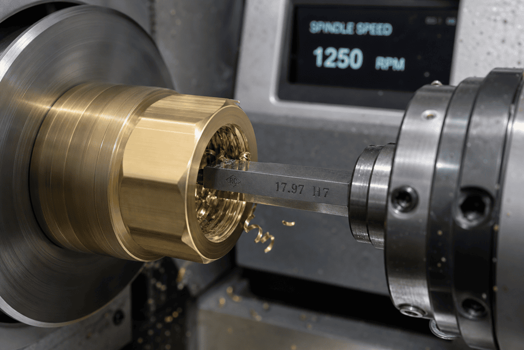
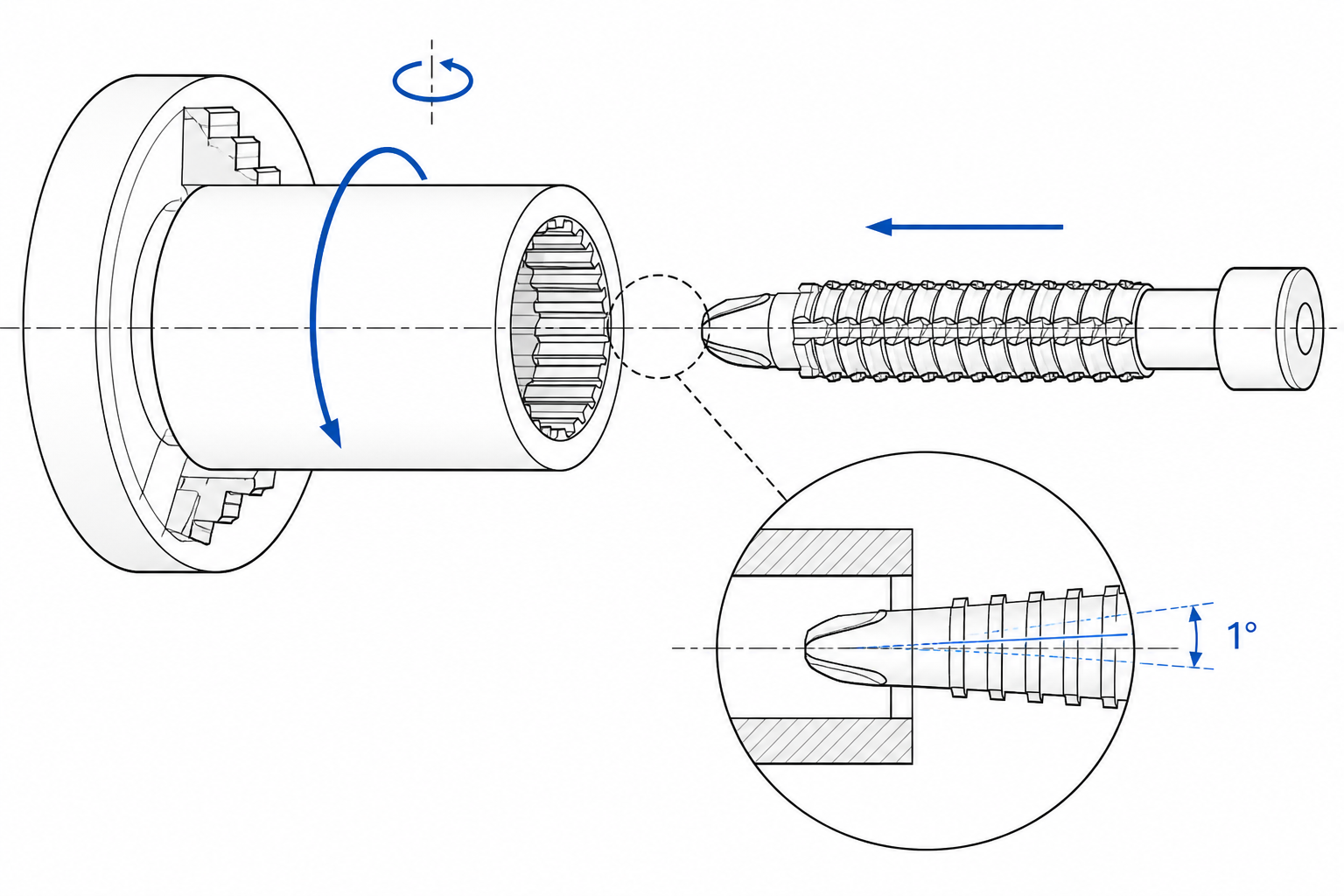
If you arrived here from milling or turning, your instinct is to compute surface speed—SFM times 3.82 divided by diameter—and work backward to RPM. Rotary broaching breaks that habit, because the tool and the workpiece rotate together. On a lathe, the spinning workpiece friction-drives the broach, which turns freely on its own bearings inside a stationary holder; on a machining center, the machine spindle drives the holder and the stationary part is cut by the wobbling tool. On a lathe, the broach and the hole rotate together at nearly the same speed, so the relative velocity at the cutting edge is a small fraction of what the workpiece RPM implies; on a machining center the workpiece is stationary and the tool alone spins, so the cutting speed is simply the tool’s surface speed at the given RPM.
The consequence, as industry technical writers on gear and spline production have pointed out, is that surface speed has very little influence on the cut. What generates the form is the combination of the broach’s 1-degree tilt—by now familiar from our complete guide to rotary broaching, which shears one corner of the polygon at a time—and the axial feed that pushes those shearing corners to depth. Spindle speed mostly controls how frequently the corners pass through the shear zone, not how much metal each pass removes. Feed is the dominant parameter; speed is a supporting actor with a hard ceiling.
That is why experienced operators tune rotary broaching the opposite way from milling: they pick a modest, stable RPM first, then spend their effort finding the highest feed the process will take without twisting the form or stalling the tool. Get that hierarchy right and the published numbers from different manufacturers stop looking contradictory and start looking like points on the same map.
The Three Parameters That Actually Matter
Every credible set of rotary broaching recommendations, whatever the exact numbers, is built from the same three parameters. Treat them as a fixed sequence and setup becomes repeatable.
- Spindle speed (RPM). The speed of whichever side rotates—workpiece spindle on a lathe, machine spindle on a mill. Manufacturers commonly publish working ranges starting around 400 RPM and extending to 3,500 RPM or more, with many shops settling in the 700–800 RPM band once the cut is stable.
- Feed rate (IPR). Inches per revolution of axial feed. This is the parameter that sets chip thickness per shearing corner. Published feeds span roughly 0.001–0.009 IPR, and the right value scales with form size and material, as the formula and table below show.
- The entry phase. The first fraction of the cut, while the form establishes itself, is where most failures are born. The common practice is to feed the first 0.005–0.010 inch at sharply reduced speed—50–100 RPM is a widely used starting point—and only ramp up toward working speed once the broach is fully engaged and synchronized with the hole.
The entry phase deserves its own emphasis because it is the one parameter conventional machining experience does not prepare you for. Until the broach’s form meshes with the hole, the tool can skid instead of shear. One rotary broaching tool supplier states the same caution from the feed side: keep the first millimeter of entry at 500 RPM or less, and accelerate only after the tool and workpiece are rotating in sync. Whether you phrase the threshold in thousandths of an inch or in millimeters, the principle is identical—slow entry, then earn your speed.
Recommended Rotary Broaching Speeds and Feeds by Material
The table below consolidates the ranges that rotary broaching tool and holder manufacturers commonly recommend. Treat every entry as a starting point for your own test cut, not a specification: form size, holder rigidity, pre-hole quality, and coolant delivery all shift the optimum. For a broader discussion of which materials take to broaching in general—including the grades that fight back—see what materials can be broached.
| Workpiece material | Typical spindle speed | Typical feed (IPR) | Notes |
|---|---|---|---|
| Aluminum | Upper end of your working range — bearing-limited | 0.004–0.009 (size-dependent) | Free-cutting; use the 0.016 × h formula at full value and let the holder’s bearing rating, not the material, set the ceiling |
| Brass / bronze | Upper end of range | 0.004–0.008 | Watch for grabbing on the free-machining grades; a slightly lower feed often improves form finish |
| Low-carbon steel | 700–800 RPM once stable | 0.002–0.003 | The classic mid-range case; enter slow and ramp up after synchronization |
| Alloy steel | 500–700 RPM | 0.001–0.003 | Reduce both parameters as hardness climbs; verify clean chip formation before speeding up |
| Stainless steel | 50–100 RPM to start, toward 700–800 RPM only when proven | 0.001 | Work hardening punishes rubbing; sharp tools and flood coolant are mandatory |
| Titanium | Conservative — treat like stainless | 0.001 | Heat concentration is the enemy; low feed, modest speed, generous coolant at the cutting zone |
Two patterns in that table are worth naming. First, the spread between aluminum and stainless is roughly a factor of four to eight in feed—the material, not the machine, decides how fast the form can be generated. Second, the stainless and titanium rows deliberately show conservative starting values, because both alloys fail slowly: the tool appears to work while edge life quietly collapses. The dedicated section below covers those two materials in detail.
How to Calculate Your Starting Feed: The 0.016 × h Rule
Rather than guessing inside a wide feed range, rotary broaching specialists publish a simple sizing formula: starting feed (IPR) = 0.016 × h, where h is the across-flats dimension of the form in inches. The formula scales feed with the size of the polygon, which is exactly what intuition demands—a 1/2-inch hex has far more corner material to shear per revolution than a 1/8-inch hex, and can carry a proportionally larger chip load.
Run the numbers for common hex sizes and something satisfying happens:
- 3/16″ hex: 0.016 × 0.1875 ≈ 0.003 IPR
- 1/4″ hex: 0.016 × 0.25 = 0.004 IPR
- 3/8″ hex: 0.016 × 0.375 = 0.006 IPR
- 1/2″ hex: 0.016 × 0.5 = 0.008 IPR
Those results land squarely inside the 0.003–0.009 IPR band that one broach manufacturer publishes as its general feed range—which tells you the published range and the formula are two views of the same data. The formula is simply the range made size-specific. This is also how the two “camps” in rotary broaching feed advice reconcile: the 0.001–0.002 IPR figures commonly recommended as a conservative starting feed, and the 0.002–0.003 IPR that another manufacturer cites for most materials, are both the same formula after applying a material-and-rigidity discount. Start below the formula on steel, at or near the formula on brass and aluminum, and never above it.
Adjust the calculated value downward—by half or more—when any of these conditions apply: stainless or titanium workpieces, thin-wall parts, long or slender tool-holding assemblies, marginal pre-hole finish, or a holder near its RPM ceiling. Every one of those conditions steals rigidity or heat capacity from the cut, and feed is the parameter that pays the bill.
Spindle Speed Limits: Your Holder’s Bearings Decide the Ceiling
Rotary broaching holders contain a live, bearing-mounted internal spindle, and that bearing assembly—not the machine and not the material—sets the absolute speed ceiling. Small holders built around 8 mm tool shanks are commonly rated by their manufacturers to roughly 3,400 RPM based on bearing design, which conveniently explains why published overall working ranges top out in the same neighborhood. Running above the bearing rating does not just risk the holder; a degraded bearing lets the broach axis wander, and the form accuracy you bought the tooling for disappears with it.
Between the floor and the ceiling, the practical working speed is decided by synchronization quality. The published guidance converges on this: one manufacturer describes 700–800 RPM as the ideal working speed for most materials, while also suggesting 500–700 RPM with feeds of 0.001–0.003 IPR elsewhere in its literature; others simply publish the wide 400–3,500 RPM envelope and let the user find the stable point. Read together, the message is that hundreds of RPM—sustained, smooth, and synchronized—is the sweet spot, and the top of the range belongs to small forms in free-cutting materials on rigid setups.
A disciplined speed ramp therefore looks like this: enter at 50–100 RPM (or at least below 500 RPM for the first millimeter), confirm that chips are forming and the tool is tracking the hole without chatter, then step the speed up in increments toward the 700–800 RPM class, re-checking form quality at each step. If twist or oversize appears at any step, drop back one increment and finish the job there—cycle time lost to a conservative 600 RPM is trivial compared to scrapping a nearly finished part. The hardware behind these limits is covered in detail in our guide to rotary broaching tools and holders.
Common Failures and the Parameter Corrections
Why is my rotary broach twisting the part or the form?
Twisting is the signature failure of rotary broaching and almost always means the tool is being asked to remove more material per revolution than the process can shear. The corrections, in the order worth trying: reduce feed—drop the IPR by 30–50 percent and watch the form clean up; reduce entry speed—a tool that skids during the first few thousandths grabs and wrenches the part once it engages; open the pre-hole—a pre-drilled hole too close to the across-flats dimension leaves excess corner material that overloads the shearing edges; and check synchronization—on lathes especially, an interrupted or stuttering spindle during entry prevents the broach from picking up the hole. Thin-wall parts twist at feeds that solid parts carry without complaint; if the wall is thin, cut the feed before blaming the tool.
Why is tool life terrible when the parts look fine?
When form quality holds but edges die after a few dozen parts, the parameters are winning the battle and losing the war—usually through heat or rubbing. First, reduce feed slightly: even a 20 percent cut lowers edge temperature disproportionately. Second, re-examine speed against the material—in work-hardening alloys, a speed too low to sustain a definite cut lets each corner rub and burnish instead of shear, hardening the surface and eroding the edge. Third, upgrade the tool material: standard M-2 high-speed steel broaches give way to powder-metallurgy grades such as PM M-4 for abrasive or higher-volume work, with coatings adding further edge life. The economic logic is simple—when tool changes interrupt a production run, the premium grade pays for itself in uptime.
What about chatter, bell-mouthed forms, and oversize hexes?
Chatter and form errors trace back to rigidity and alignment rather than speed and feed arithmetic: check holder runout, concentricity of the pre-hole with the spindle, and whether the broach shank is seated fully on its internal taper. That said, parameters still matter at the margin—chatter that survives mechanical fixes usually yields to lower RPM with unchanged feed, because it drops the excitation frequency of the shearing cycle. Bell-mouthed entries are the entry phase mismanaged: the first 0.005–0.010 inch was fed too fast or too slow, and the correction is the disciplined slow-entry ramp described above.
Stainless and Titanium: The Slow-and-Cool Discipline
Stainless steels and titanium alloys reward a different temperament. Both work-harden at the shearing edge, and titanium adds poor thermal conductivity—heat that would flow into the chip in steel concentrates in the tool edge instead. The standard discipline, consistent across manufacturer guidance, has three parts: feed low enough to guarantee a definite cut (about 0.001 IPR in stainless, so every corner takes a real chip rather than burnishing the surface); speed developed conservatively (start at 50–100 RPM, prove clean chip formation, then step up toward the 700–800 RPM class only if the process stays stable); and coolant delivered directly to the cutting zone, generously and continuously, because intermittent coolant is arguably worse than none—it thermal-cycles the edge.
Tooling choices carry equal weight here. Powder-metallurgy grades such as PM M-4 hold their edge in the gummy, work-hardening conditions where M-2 rounds over, and heat-resistant coatings help on higher-speed versions of the process. Sharp is non-negotiable: a dull edge in stainless does not cut worse, it cuts and hardens, so regrind on a schedule determined by parts count, not by visible wear. Shops that respect this discipline routinely rotary broach stainless fittings and titanium aerospace components; shops that treat 17-4 PH like 1018 do not, and usually conclude—incorrectly—that the process does not work in these materials.
Rotary Broaching Speeds vs. Linear Broaching Speeds
Confusion between the two broaching families is common, and it matters for parameters because the two processes use different speed logic entirely. Linear (conventional) broaching is specified in surface feet per minute, with cutting speeds commonly cited in the 20–120 SFPM range depending on material and whether the pass is roughing or finishing—the broach’s full row of teeth engages sequentially, and speed directly sets chip load per tooth and heat input. Rotary broaching, as covered above, is specified in RPM and IPR, with a synchronized single-corner shear in which feed dominates and surface speed barely matters.
The practical takeaway: you cannot port a SFM number from linear broaching literature onto a rotary setup, and vice versa. If you are weighing the two processes against each other for a part, the full comparison—capability, depth limits, batch economics—lives in our article on rotary broaching vs. conventional broaching, and the parameter logic specific to the linear side is treated in broaching speed vs. feed. For process fundamentals, start with what broaching is and how the linear process generates a form in a single stroke.
Frequently Asked Questions
What RPM should I use for rotary broaching?
Published working ranges span roughly 400–3,500 RPM, but the widely cited ideal band is 700–800 RPM for most materials once the cut is stable—with 500–700 RPM as a common conservative choice in harder alloys. Always enter the hole at far lower speed (50–100 RPM, or at least below 500 RPM for the first millimeter) and ramp up only after the tool synchronizes. The absolute ceiling is your holder’s bearing rating: small 8 mm-shank holders are commonly rated to about 3,400 RPM, and no material justifies exceeding it.
What feed rate should I use for rotary broaching?
Calculate a starting feed with the rule IPR = 0.016 × h, where h is the across-flats dimension of the form: that yields about 0.003 IPR for a 3/16″ hex and 0.008 IPR for a 1/2″ hex. Apply the full value in aluminum and brass, discount it to 0.002–0.003 IPR in carbon and alloy steels, and drop to about 0.001 IPR in stainless and titanium. If the form twists, feed is the first parameter to reduce.
Why is my rotary broach twisting the workpiece?
Twisting means the shearing action is being overloaded. In order of likelihood: feed too high for the material or wall thickness (reduce IPR by a third to a half), entry too fast for the tool to synchronize with the hole (enter at 50–100 RPM), pre-hole too small (open it toward the recommended clearance over across-flats), or insufficient rigidity in the holder or part setup. Thin-walled parts are especially prone and often need feeds well below the standard formula.
Do I need coolant for rotary broaching?
Yes for production work, and unconditionally yes in stainless and titanium. Although rotary broaching is a low-speed, low-force process compared to milling, the shearing edges still concentrate heat in a small zone, and work-hardening alloys punish a hot, rubbing edge with rapid wear. Flood coolant delivered to the cutting zone is the default; in titanium, generous and continuous application is one of the three pillars of the process, alongside low feed and conservative speed development.
When Speed and Feed Tuning Isn’t Enough
Good parameters solve the problems that belong to rotary broaching—but they cannot move the process’s structural limits. If your form depth exceeds roughly twice the broach diameter, if the cross section is large or the engagement long, or if part volumes have grown to where even a fine-tuned 700 RPM rotary cycle becomes the bottleneck in the cell, the answer is no longer a better feed rate. It is a different process: conventional broaching, where a multi-tooth broach generates the complete form—deep splines, long keyways, large hexes—in a single stroke measured in seconds, at production rates no in-cycle rotary operation can match.
We manufacture that next step. Our broaching machines cover internal and external forms across the range that rotary tooling leaves behind, and our engineering team sizes machine, broach, and process together from your part print. When your hexes outgrow the wobble, that is the conversation to have.