A valve body is two things at once: a pressure boundary and the structural frame of a sealing system. The gate or disc that closes the flow rides on machined features inside the body cavity, the seat that seals against it is carried by a machined pocket or ring, and the stem, bonnet and flange connections all reference surfaces cut into a casting that arrived from the foundry with a skin and a few millimeters of stock. In water supply, fire protection, HVAC and general industrial piping, these parts are made in volumes that rival automotive components — production fitting lines run millions of pieces per year across the valve and fitting clusters that dominate global pipe-component supply.
That combination — repeating internal features, near-net castings, extreme batch sizes — is exactly the profile where broaching earns a place on the process plan. A single stroke can generate a seat pocket floor, a pair of guide slots, or an internal gland recess with the complete form ground into the tool, identically on every part in the run. At the same time, valve manufacturing has an honest boundary that any process planner already knows: the final sealing interface on most designs is finished by turning, grinding or lapping, not by broaching. This article respects that boundary. It maps which features on a valve body or pipe fitting are realistic broaching candidates, which belong to other processes, and how the broached features are produced reliably in casting materials at fitting-line volumes.
We start with the part families and their feature maps, then work through sealing grooves and wedge pockets, casting-skin cutting strategy, fixturing irregular bodies, and the batch economics against milling. It follows the same workpiece-case format as our articles on brake caliper broaching and cylinder block broaching — the other casting-family cases on this site.
The Valve Body as a Machining Problem
Gate, Globe and Butterfly: A Feature Map
For process planning, the three dominant families break down into a short list of feature groups:
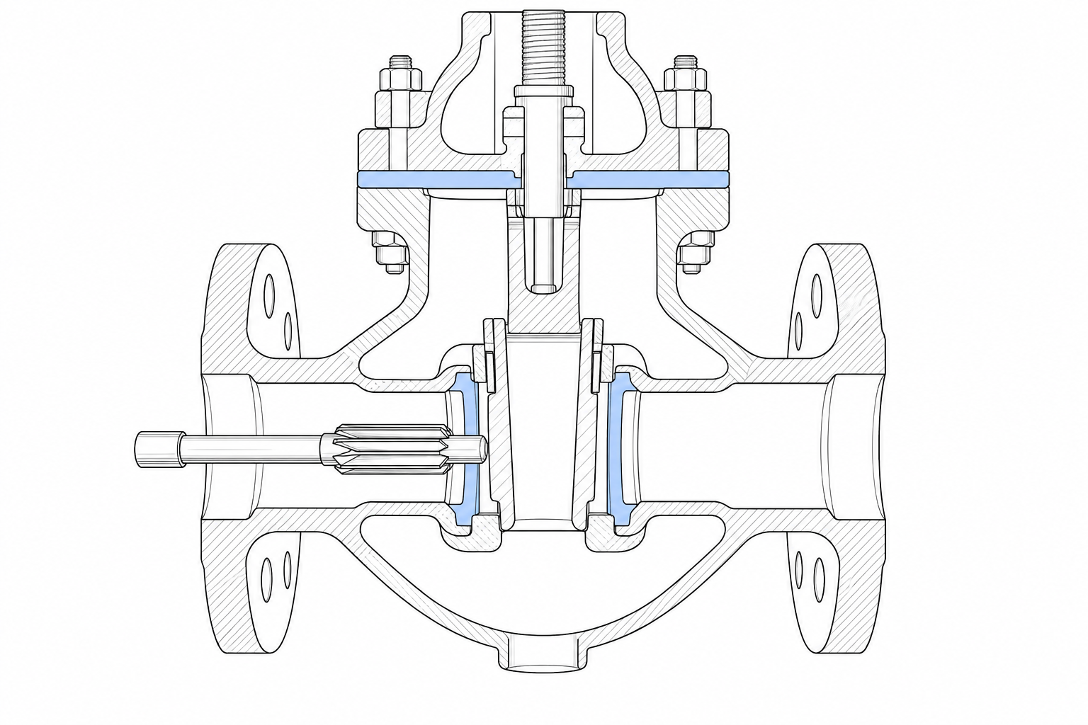
- Gate valve bodies. A flow bore through the ends, an internal wedge pocket that receives the gate, two seat faces where the gate seals, guide rails or support ribs along the pocket that control gate travel, a stem bore with stuffing box above, and flanged, threaded or grooved end connections.
- Globe valve bodies. A flow path with a sharp turn, a seat pocket at the throat that carries the seat ring or seal, a disc guided by a stem and bushing, a bonnet flange, and the same end-connection families.
- Butterfly valve bodies. A short through-bore with a centered seat groove or liner retainer, two transverse shaft bores, and shaft-end features for the actuation interface.
- Pipe fittings. Elbows, tees and couplings in malleable iron and bronze, with internal flange faces, socket or spigot recesses, and — in grooved-coupling systems — defined internal and external groove geometry.
The Volume Reality
Most of these parts are gray or ductile iron, malleable iron, bronze, brass and cast steel castings, arriving near-net-shape with machining allowance concentrated on functional features. The production culture mirrors fitting-industry economics: long runs of a limited part-number range, dedicated equipment, cycle time measured in seconds per piece, and cost per part defended aggressively. Small-diameter water and fire-protection valves and fittings sit at the highest volumes; larger cast-steel gate and globe bodies for oil and gas service run smaller batches with heavier walls. Both ends of that spectrum contain features that repeat identically on every casting — which is the signal broaching looks for.
What Broaching Actually Does on a Valve Body
The features on a valve body or fitting that realistically fall to broaching are grooves, pockets and internal faces with a defined form — framed here as candidates, because every valve design distributes work differently:
- Gate pocket guide features. The guide slots, rails and pocket floor lands on which the gate rides and wedges. Where these are prismatic rather than fully profiled, a surface or internal broach generates them in one pass with side relationships designed into the tool.
- Seat pockets and retaining grooves. The counterbore floor and retaining groove that carry a seat ring or seal cartridge in globe and gate bodies — defined-width, defined-depth groove forms that repeat on every part.
- Stuffing box and gland recesses. Internal grooves in the stem bore region — the packing retainers, lantern-ring seats and O-ring grooves whose cross-section consistency sets seal compression.
- Internal flange faces and stops. Facing and step features inside fitting bodies — socket bottoms, flange faces and locating stops — where a defined surface must be produced at volume.
- Flat seat machining on non-ferrous parts. Finishing flat seating faces on copper-alloy valve and fitting components — a production application our own pipe main valve broaching machine was built around, covered below.
The boundary is just as important. The final sealing interface on a seat face — the mirror that the gate, disc or globe presses against — is produced by turning, grinding or lapping, because the requirements there are surface finish and geometry at a level those processes own. The flow bore belongs to boring or turning. Stem bores and their precision fits are turned, bored and reamed. Butterfly valve seat grooves are circular profiles turned in one setup with the bore. Threaded connections are cut or rolled, never broached. A sourcing engineer reading a “valve broaching” scope should read it as grooves, pockets and defined internal or flat features on the body — never as a proposal to broach the sealing interface itself. That division of labor comes first in every scoping conversation we run.
Sealing Grooves and Wedge Pockets: Why Form Consistency Matters
A soft seal — an O-ring, a compressed packing set, an elastomer seat cartridge — works on compression. It seals because the groove that houses it has a defined depth and width, so the ring is squeezed by a controlled percentage of its section, everywhere around its circumference, on every part. Groove depth scattered across a production run means compression scattered with it: deep grooves leak under low pressure, shallow grooves over-compress, take permanent set and fail early. The same logic governs the guide features in a gate pocket — rails cut inconsistently to the seat reference make the gate wedge unevenly, and uneven wedging is uneven sealing.
This is precisely what broaching is built to deliver. Every dimension that matters — groove width, flank angles, corner radii, depth steps, the relationship between two guide slots cut in the same pass — is ground into the tool once, and every part receives that same form from the same finishing teeth. Part-to-part variation tracks the slow, predictable wear of the tool rather than accumulating the setup-to-setup differences of multi-pass cutting. A broached retaining groove for a seat ring is dimensionally the same groove on casting number one and casting number ten thousand.
The honest complement to that strength: broaching generates the form, and where the design demands a lapped or ground sealing finish, those operations stay in the chain — broaching can carry semi-finishing teeth that leave a controlled, uniform allowance for them. The two processes are sequential allies, not competitors. A turning or grinding operation that receives a broached groove with consistent stock on every part runs far more stably than one fighting cast-to-cast variation.
Broaching Castings: Skin, Interrupted Cut and Tooth Rise
Valve bodies and fittings are castings, and casting changes the cutting problem in three specific ways — the same three covered for the sister casting families in our what materials can be broached reference and the brake caliper case.
The skin. The first teeth into the work meet a surface the finishing teeth never see: foundry scale, sand inclusions, and locally chilled hard spots where the melt cooled against the mold. The tool answer is roughing teeth with enough rise per tooth to cut beneath the skin rather than ride along it, tough edge preparation, and carbide tooth material on modern broaches. Skimping on tooth rise to protect the tool backfires — a tooth that rubs the abrasive skin dulls far faster than one that cuts beneath it.
The interrupted cut. Inside a valve body the broach frequently passes through open cavity — cutting, leaving material at a cross-rib or web window, cutting again. Every entry is an impact on the cutting edge. Pitch selection keeps two or more teeth in cut through the interruptions so the load never drops to zero and hammers back in, and gullet geometry clears the short, broken chip the interruption produces. Bronze and brass cut cooler and more forgivingly than iron; cast steel is tougher and demands stronger tooth geometry and moderate speeds.
Material scatter. A single valve family may span gray iron, ductile iron and bronze across its size range, and the broach set must respect that: tooth counts, chip loads and speeds are specified against the actual material certification, not a family average. This is standard input to broach design on every casting program we quote — the same discipline applied across the cast brake caliper and cylinder block programs described elsewhere on this site.
Fixturing the Irregular Body: Datums from the Raw Casting
A valve body is the opposite of a friendly workpiece geometry: an irregular shell with an internal cavity, thin walls in the bonnet region, and no machined surface to locate on the day it reaches the broaching station. Fixturing it is half the process, and two disciplines carry most of the weight.
Datum discipline from the raw casting. The foundry provides the first references — locating pads, core prints, or the cast flow bore itself — and the opening operations establish the machined datum system everything downstream must follow. A broached groove referenced to that datum scheme inherits only tool wear; a groove referenced casually to the skin inherits cast-to-cast scatter that no tool can cut out. On fitting lines the datum scheme is usually locked to the flow bore axis and one end face, because that is the reference the sealing system is built on — the seat must be square to the bore, and so must everything that positions the gate or disc relative to the seat.
Support against the cut without distortion. Broaching force is directional and substantial, and a valve shell has compliant zones. The fixture closes the force loop through stiff material: nest supports under the body cored walls and around the flanges, stops that take the cutting force in compression against solid casting, and clamps positioned opposite supports — never bridging a cavity wall with air behind it. Thin-walled bronze and malleable iron fittings are particularly sensitive: a clamp that bells the body even slightly lets the broach cut the groove true on the deflected part, and the geometry walks away when the clamp releases. Clamp-force budgeting, chip evacuation through the cavity, and multi-part staging for small fittings are exactly the topics our broaching fixture design guide works through in detail.
Batch Economics: Stroke Time Against Milling
The fitting and valve industries live on cost per piece, so the process decision reduces to a comparison the engineers on both sides already know. Cutting a guide slot pair or a seat-retaining groove by milling means multiple tool passes, often multiple setups, and cycle time that scales with feature length and depth. Broaching removes the total stock in one stroke whose duration is set by stroke length and speed — and the stroke does not lengthen when the groove gets wider or the form more complex, because the form lives in the tool. On a defined part running in the tens of thousands per year, the per-part cost curve for broaching drops below milling early and keeps dropping as volume rises.
Tool economics follow the same logic. A form broach is a high-value, long-life tool — its cost amortizes over thousands of parts between reconditionings, and a rotating spare keeps the machine running while the production broach is reground off-line. Milling spread across the same features pays continuously in inserts, setup labor and in-process variation. The honest reverse: below the volume threshold, or across many short-run part numbers, a machining center running milling programs is the more economic answer, and a broach specification should never be forced onto it. The break-even is calculated against real drawings and real annual volumes, not asserted — which is how we scope every inquiry.
The Pipe Main Valve Broaching Machine
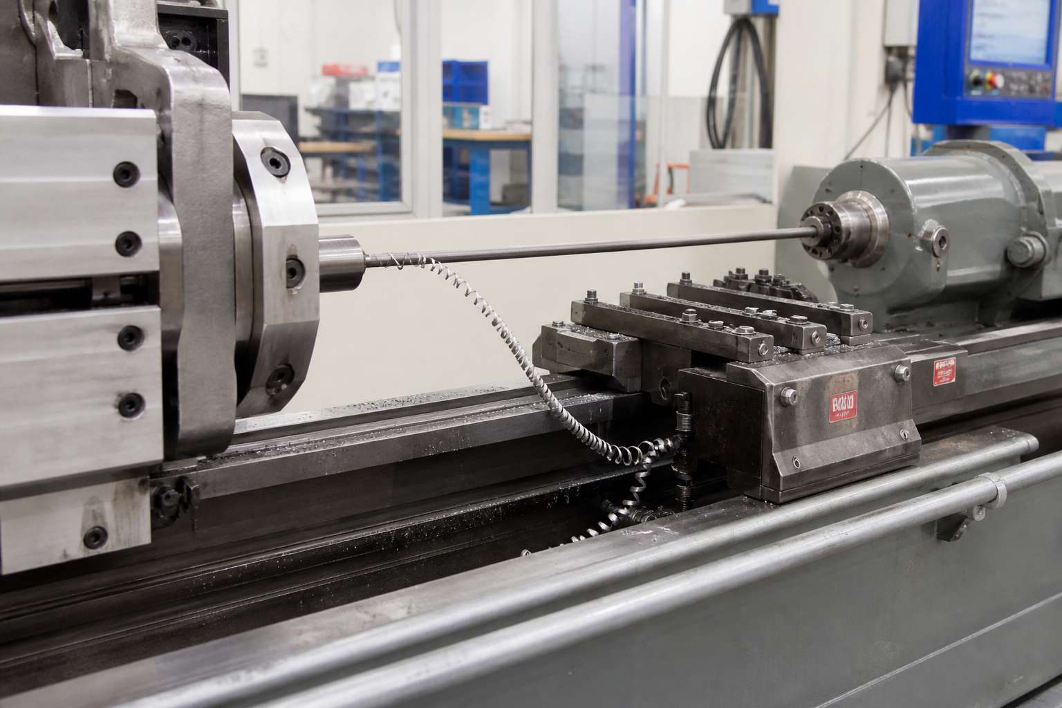
When the feature list and volumes point to broaching, the machine follows the workpiece. Valve and fitting features mean internal grooves and pockets inside shell castings — work that demands rigid guidance of a long tool through an interrupted cut, and multi-station construction that keeps loading time hidden inside cutting time. That is the configuration behind our pipe main valve broaching machine: a special-purpose broacher built for valve and pipe-component features, with full-stroke broach guidance so the tool is supported through the entire cut, and a multi-station design that stages parts so one stroke is always working while the next part loads.
Its production application on non-ferrous pipe components is flat seat-surface machining on copper-alloy valve seats — producing defined seating faces at accuracy and efficiency levels that brought broaching in specifically to cut manufacturing cost on those parts. The same platform logic extends across the valve-family feature list above: seat pockets, retaining grooves, guide features and internal flange faces in iron, steel and bronze bodies. Our engineering team scopes the fixture, broach set and station count against your part drawings, material specification and annual volumes, and returns stroke and cycle time worked out against the actual casting.
The Casting Family: Related Cases on This Site
Valve bodies sit in the same workpiece family as the other casting cases documented on this site, and the shared problems are why the engineering transfers. The brake caliper case covers cast-skin strategy and thin-wall fixturing on the interrupted geometries typical of automotive castings. The cylinder block case covers the largest-scale end of the family — full-face finishing and formed joint features at engine volumes. Valve and fitting work draws on both: caliper-scale part handling and wall-thickness care, block-scale process discipline and form consistency, at fitting-industry volumes. The complete machine portfolio behind these applications — vertical, horizontal, servo and surface configurations — is overviewed on the broaching machines page.
Frequently Asked Questions
Are valve bodies broached?
Specific features on them, yes — the body as a whole, no. Guide slots and pocket lands in gate bodies, seat-ring retaining grooves, stuffing box and gland recesses, internal flange faces and stops, and flat seating faces on copper-alloy parts are established broaching candidates at production volumes. The flow bore, stem bores and threaded connections are machined by turning, boring and threading, and the final sealing interface is finished by turning, grinding or lapping. Broaching takes the repeating groove and pocket features; it does not take the bore-and-finish backbone of the valve process.
What features of a valve body can be broached?
The realistic candidates are defined-form internal features: gate pocket guide slots and floor lands, seat pocket counterbore floors and retaining grooves for seat rings or seal cartridges, packing and O-ring grooves in the stem bore region, internal flange faces and locating stops in fittings, and flat seat surfaces on copper-alloy components. Which of these actually go to broaching on a given design depends on the drawing and the annual volumes — it is a candidates list evaluated feature by feature, not a universal claim.
Can cast iron valve bodies be broached?
Yes — gray, ductile and malleable iron are routine broaching materials, as are bronze, brass and cast steel valve bodies. Iron demands roughing teeth with enough rise per tooth to cut beneath the foundry skin, robust edge preparation and carbide teeth; interrupted cuts through cavity ribs and windows are handled with pitch selection that keeps multiple teeth engaged. Cast steel is tougher and runs at moderate speeds with stronger tooth geometry; bronze and brass cut freely at higher speeds. The material specification is one of the first inputs to broach design on any valve program.
Does broaching produce the sealing surface itself?
Generally no — and the distinction matters. Broaching produces the grooves and pockets that house and position seals, where its advantage is form consistency from part to part. The final sealing interface that the closure member presses against is normally finished by turning, grinding or lapping to reach the surface finish and geometry those processes control. Where a design does call for a broached sealing-grade face, semi-finishing teeth leave a controlled uniform allowance for the finishing operation. The two work as sequential allies: broaching stabilizes the form, the finish operation perfects the interface.
If you manufacture valve bodies or pipe fittings and have grooves, pockets or seat features on the drawings that repeat at volume, that is exactly the work we engineer around. Send the part drawings, material specification and annual volumes, and we will return a machine, fixture and broach configuration with stroke and cycle time calculated against your casting. Start with the pipe main valve broaching machine page, or contact our engineering team directly with your workpiece details.