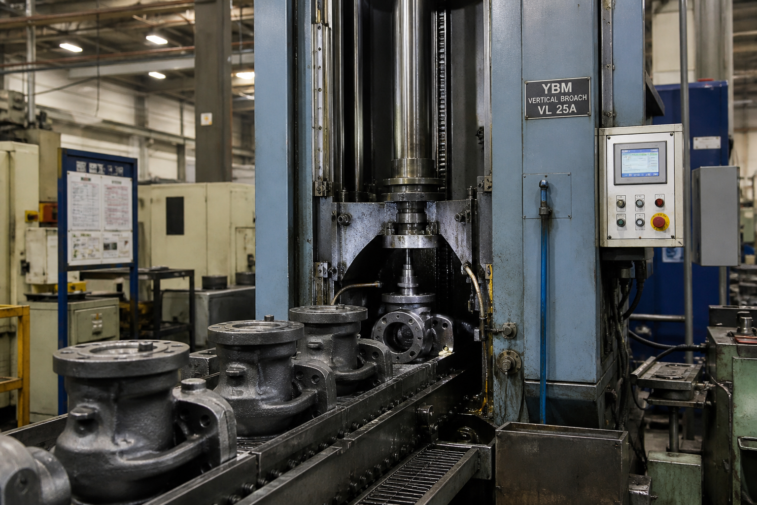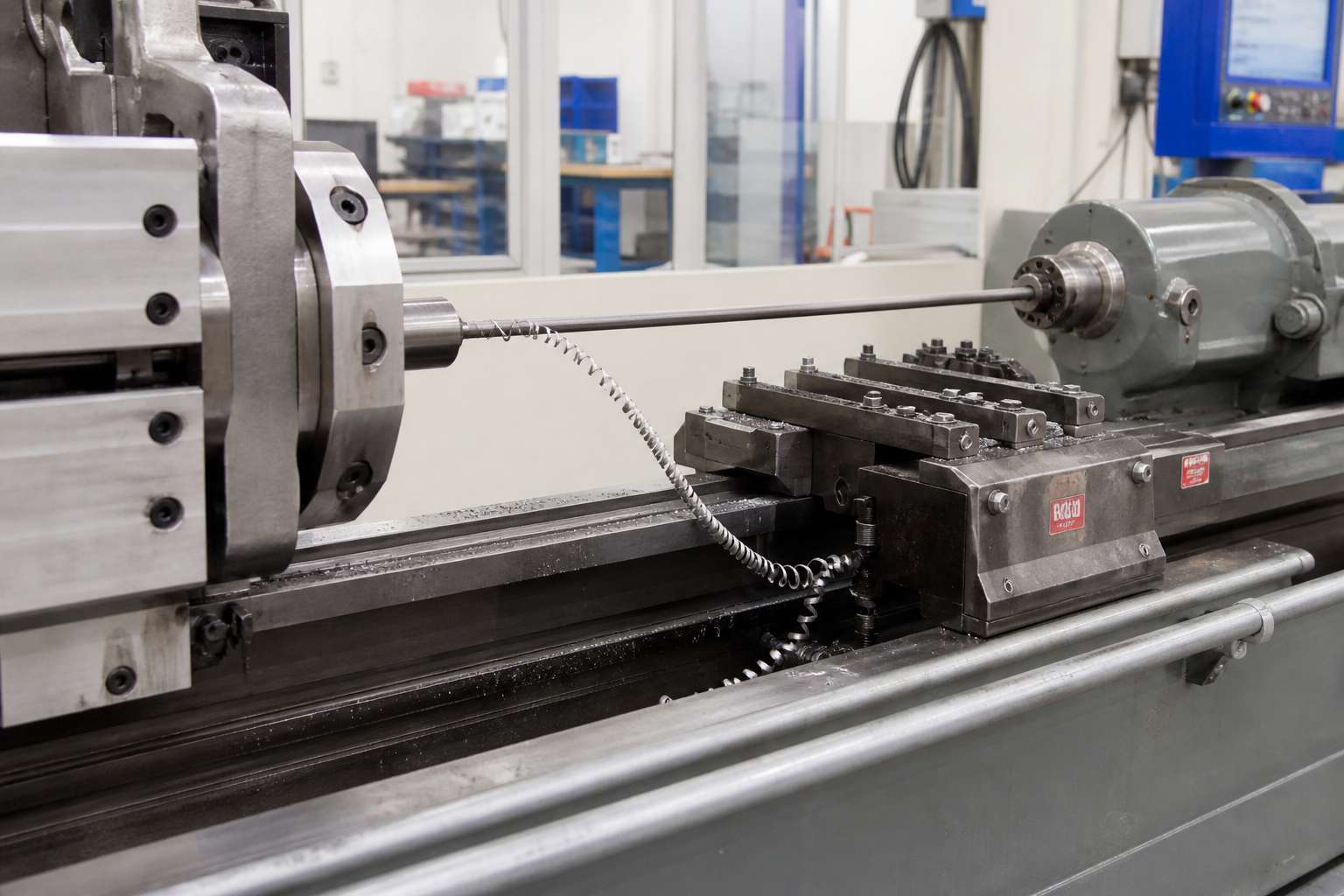
On a crankshaft line, the rough-machining cell has one job: turn a forged or cast blank with lumpy, uneven stock into a shaft whose journals, fillets, and thrust faces are ready for heat treatment and final grinding — at line rate, part after part. Turn broaching is the process many high-volume engine plants choose for that cell. The workpiece rotates the way it does on a lathe, but instead of a single cutting edge tracing the profile, a broach-type cutter carrying many teeth sweeps around each journal, and the journal’s features — OD, fillets, thrust walls, seal surfaces — come out complete in one coordinated orbit.
This guide covers the mechanism, the two machine concepts, crankshaft and camshaft applications, tooling, the comparison against turn-turn broaching, external milling, and CBN grinding, and dry cutting practice. If you are new to the family, start with our primer on what broaching is; this article stays on the rotating-workpiece branch.
What Is Turn Broaching?
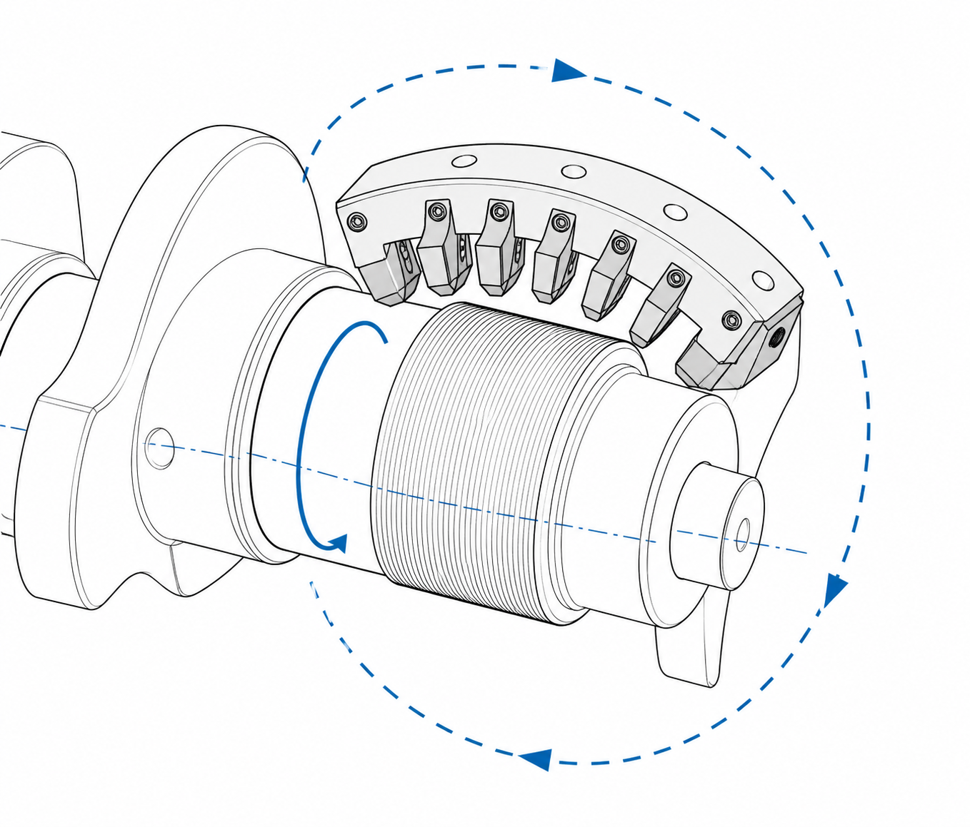
In turn broaching, the workpiece — almost always a crankshaft or camshaft — is held between centers or in chucks and rotated about its axis at a controlled speed. The “broach” is not a long bar pulled through a hole. It is a short cutting assembly carrying a series of teeth, mounted on a carrier that sweeps along the rotating journal surface. As the workpiece turns, each tooth enters the cut, takes a small fixed chip, and leaves; the next tooth, set slightly deeper or placed to cut a different band, follows. One orbit is enough for every tooth to contribute its slice, and the finished journal is the sum of them all.
The clearest way to understand the process is to set it against its two relatives. In conventional (linear) broaching, the workpiece is clamped stationary and a multi-tooth tool is pushed or pulled past it in a straight line; the teeth rise progressively, and one pass takes the feature from blank to finished form. That is the logic of our surface broaching machine guide — and turn broaching is that same logic rolled onto a rotating cylinder. The tool path is an orbit rather than a straight stroke, yet each tooth still owns a fixed depth of cut, and the form is still built into the tool rather than generated by machine motion.
Against turning, the difference is the number of edges and who owns the profile. A turning operation uses one (or a few) continuously engaged edges, with journal geometry generated by axis interpolation — accuracy depends on the machine’s dynamic response, thermal behavior, and wear compensation. Turn broaching distributes the profile across dozens of teeth, each ground to a fixed depth and a fixed band of the surface, so the form lives in the tool. Wear spreads across many edges instead of concentrating on one, and part-to-part variation tracks the slow, predictable wear of the tool set rather than the moment-to-moment behavior of an interpolating axis.
Three properties follow, and they explain the process’s place on engine lines: forming consistency inherited from the tooling; multiple features cut in one setup against one datum; and short engagement per tooth — each edge cuts for a fraction of the cycle and cools the rest — which keeps edge temperatures down and makes dry cutting practical.
Two Machine Concepts: Linear and Circular Turn Broaching
Turn-broaching equipment falls into two structural families, usually described as linear (or straight-blade) and circular (or rotary-head) concepts. The naming is not standardized across builder literature — “rectangular,” “tangential,” and “rotary” all overlap — so identify a machine by its kinematics, not its label.
Linear (straight-blade) turn broaching
Here the cutter is a straight bar or plate carrying a row of teeth, arranged along the workpiece axis and rising in depth along the row. The blade is mounted on a slide assembly that plunges toward the journal and then travels axially, so the tooth row sweeps the full journal width while the part rotates beneath it. Conceptually it is the closest cousin of turning: the single tool on a lathe’s slide replaced by a bar of “pre-programmed” teeth, each a frozen increment of what would otherwise be a long feed motion. The construction is straightforward, stiff, and easy to access for setup and inspection.
Circular (rotary-head) turn broaching
In the circular concept, the teeth are mounted around the periphery of a large ring-shaped cutter disc. The disc rotates about its own axis, and its teeth enter and leave an engagement arc against the spinning workpiece — a rolling engagement rather than a sliding stroke. Because several teeth work in the arc at once, the cutting force waveform is smooth and the process wraps the journal rather than traversing it. Two consequences matter on a production line: tool inspection and insert changes happen on the far side of the disc, outside the cut, so servicing hides inside the machine cycle; and the ring format invites opposed cutter heads — one above, one below — whose radial forces largely cancel, loading the workpiece in balance instead of bending it. On long, slender crankshafts, that balance is a real contributor to holding journal geometry.
Which concept a line uses comes down to part mix, cycle time, and layout. What both share — rotating workpiece, many fixed teeth, form carried by the tool — is what makes them turn broaching.
Crankshaft Application: Journals, Fillets and Thrust Faces in One Setup
The crankshaft is the process’s flagship application, and it is worth being precise about where turn broaching sits in the routing: it is a soft-state operation. A typical line runs blank preparation and centering, turn broaching of the journals, oil-hole drilling, induction hardening, and grinding to size. Turn broaching removes the bulk of the stock and establishes the geometry heat treatment and grinding inherit — its job is to hand the grinders a journal that is round, concentric, consistent, and carrying a small, uniform grind stock.
Main journals. The main journal ODs, both side fillets, and the thrust wall faces that set axial position are natural turn-broached features: surfaces of revolution about the crank axis, exactly what an orbiting multi-tooth cutter generates. Because all mains are cut in the same setup against the same rotational datum, their mutual concentricity comes from machine geometry and the tool set — not from the stack-up of successive setups. Relationships between features are cut in, not assembled from fixture-to-fixture repetition.
Rod journals. The connecting-rod journals are offset from the axis and distributed at phase angles around it, so as the crank spins they travel on their own orbits. The cutter carrier must track that orbit, keeping its cutting arc centered on the rod journal rather than the main axis — on modern machines a multi-axis CNC interpolation, with phase locked by angular indexing of the workpiece. Roughing the rods in the same clamping as the mains is what makes the process attractive: phase angle and throw are established against one datum.
Fillets. The fillet radius where each journal meets its web is the fatigue-critical location of the shaft — where bending stress concentrates and where induction hardening and fillet rolling later do their strengthening work. In turn broaching the fillet form is ground into dedicated teeth and copied onto every part identically. That consistency is not cosmetic: it conditions how uniformly the hardening and rolling treatments act, and a process that varies the fillet part-to-part hands that variation straight to fatigue life.
Seal journals and flange faces. The flywheel flange and the seal running surface are also surfaces of revolution and commonly join the same pass family, leaving only grind stock for finishing. Broaching reaches deep into the rest of an engine plant, too — our articles on cylinder block broaching 그리고 connecting rod broaching cover the stationary-workpiece side of the family.
Camshaft Application: Base Circles and Journals — an Honest Boundary
Camshafts share the crankshaft’s rotating-workpiece format, and the features turn broaching handles well are the true surfaces of revolution: the journal ODs and the base circles of the cam lobes. On high-volume cast-iron lines, turn broaching (or its turn-turn variant) is an established way to cut these diameters fast and consistently, leaving uniform stock for finishing.
The honest boundary is the cam lobe itself. The lobe profile is a non-circular, variable-velocity contour, and the accuracy, waviness, and finish the valvetrain needs from it are delivered by cam grinding — final lobe geometry lives there on essentially every production line. Some routings rough the lobe flanks by milling or broaching-type cutting before the grinder, but turn broaching does not finish cam profiles, and a supplier who says otherwise is overselling. Materials reinforce the boundary: cast camshafts are often chilled in the lobe region, so the flank presents a hard white-iron skin exactly where a cutting edge would have to work. For tool-material perspective on cutting difficult workpieces with broaching tools, see our article on broaching titanium and superalloys. (Assembled steel camshafts, joined near the end of the process, follow different routings again; the above describes the one-piece cast line.)
Tooling: Cutter Carriers, Indexable Inserts and Broach Segments
The tooling stack has three levels. At the top, the carrier — the cutter disc or blade with its holding mechanism and machine interface. Below it, cutter cartridges or holders, each seating one cutting element at a defined radial and axial position, with shim and adjuster hardware for position setting and size compensation after regrinds. At the bottom, the cutting element itself — and here the industry splits into two solutions.
Indexable coated inserts. Each tooth carries a coated carbide insert, clamped in its cartridge. When an edge wears, the insert is indexed to a fresh corner or swapped, and the tool is back in specification in minutes — no regrinding loop, no tool leaving the plant. The coatings act as heat barriers, which lets these inserts run dry at the speeds a rotating workpiece delivers (workpiece rotation, not a hydraulic stroke, generates the cutting speed here). Insert tooling dominates modern crankshaft lines because maintenance collapses into pocket-level logistics.
Solid broach segments. The alternative is integral, ground tooth segments — classic broaching construction shrunk onto the turn-broaching carrier. Solid segments offer maximum stiffness and form accuracy, which matters most on finishing zones and fillet form teeth. Their maintenance is the traditional model: at end of life the segment is reground and recoated, and the size lost is put back with shims or machine compensation — the same regrind-and-compensate economy that keeps conventional broaches alive for decades.
Mixed tool sets are common — inserted teeth where stock removal is heavy, solid form teeth where geometry is sacred. Either way the discipline is identical: track life by tooth position and service on schedule, not on failure.
Turn Broaching vs. Turn-Turn Broaching, External Milling and CBN Grinding
Turn broaching is one of four processes competing for the crankshaft routing. The table is deliberately qualitative — specific cycle and tolerance numbers belong to specific machines, part families, and material conditions, and quoting them generically would be guesswork.
| Process | How metal comes off | Flexibility | Typical role on a crankshaft line |
|---|---|---|---|
| Turn broaching | Many fixed teeth on a disc or blade sweep the rotating journal; each tooth owns a fixed depth and band | Low — tooling is part-specific | High-volume soft-state roughing and semi-finishing of journals, fillets, thrust faces; fast, highly consistent |
| Turn-turn broaching | Roughing by turning (absorbing uneven forging stock), finishing by broaching, in one machine | Moderate | Shafts with scattered blank stock; pairs turning’s forgiveness with broaching’s consistency |
| External milling | An enveloping milling cutter wraps the journal under CNC control, tooth by tooth | High — changeover is a program change | Multi-product lines and medium volumes; slower per part but retooling-free for new variants |
| CBN grinding | A CBN wheel removes stock directly — after hardening, or increasingly from the soft blank | Medium — wheels are part-family-specific | Final size, finish, and fillet integrity; grind-from-blank routings skip prior cutting entirely |
The selection logic reduces to three questions. Volume versus variety: one crankshaft design at automotive volumes amortizes dedicated broach tooling and wins on cycle time and consistency; several variants from the same machines points to milling, where a new part is a program, not a tool set. Blank condition: heavily scattered forging or casting stock punishes a pure broaching pass with uneven chip load — exactly the gap turn-turn broaching fills, using a turning pass to normalize the stock before the broaching teeth finish. Finishing strategy: if the plant finishes on CBN grinders, roughing only needs to deliver uniform grind stock, which plays to turn broaching’s strengths. For a general treatment of the trade-off across feature types, see broaching vs. milling.
Dry Cutting and Coolant Strategy on Crankshaft Lines
Turn broaching is one of the few heavy-metal-removal processes that runs dry as a matter of routine, and the reasons are structural. Each tooth is engaged for only a fraction of the machine cycle and of its own orbit around the carrier — the rest of the time it air-cools. The cutting speed comes from workpiece rotation and lands where coated carbide is designed to work. Together, these hold edge temperatures within the tolerance of modern insert grades, where continuous engagement would cook the same edge.
The plant-level payoff is bigger than the tool room. Dry cutting produces clean, unmixed chips — on a steel crankshaft line they go back to the melt at full value — and it deletes the coolant system’s purchase, filtration, maintenance, and disposal liabilities along with the oil mist in the cell’s air. Where pure dry cutting is not ideal — chip evacuation from confined shoulders, certain alloy behavior — minimum quantity lubrication (MQL) supplies just enough lubricant at the edge to keep chip flow and finish under control without a flood-coolant infrastructure. Flood coolant survives in some installations, but as the exception, usually inherited from legacy constraints rather than chosen.
Machine Platforms: Where Turn Broaching Sits in the Broaching Family
A turn-broaching machine — sometimes called a turn-broaching center, more often just a specialized station inside a crankshaft or camshaft transfer line — combines a workpiece drive with headstock and tailstock centers, numerically controlled cutter carriers, and integrated loading and gaging. It is built around one part family, and that is the honest way to see it: not a configuration of a general-purpose broaching machine, but the broaching method — many fixed teeth, form carried by the tool — specialized onto rotating workpieces.
Within the family tree, the lineage is direct: internal broaching cuts keyways and splines inside bores with a tool drawn through the part; surface broaching cuts external flats and contours with a tool stroked across a clamped part; turn broaching wraps that same external-surface logic around a rotating part. As a manufacturer rooted in the family — from standard 브로칭 머신 through part-specific tooling — we treat turn-broaching-type work as the orbital branch of the same tree: the architecture changes to suit the rotating workpiece, but the tooling discipline, form-copying economics, and reconditioning model are the ones we apply across the range.
Frequently Asked Questions
What is turn broaching?
Turn broaching is a metal-cutting process in which the workpiece — typically a crankshaft or camshaft — rotates about its axis while a multi-tooth broach-type cutter sweeps along the journal surfaces. Each tooth removes a fixed depth, so the form is built into the tool. In one setup it cuts journal ODs, fillets, thrust faces, and seal surfaces, which is why it anchors the rough-machining cell on high-volume engine component lines.
What is the difference between turn broaching and turn-turn broaching?
Plain turn broaching removes all the stock with broaching teeth. Turn-turn broaching adds a preliminary turning pass in the same machine: turning normalizes uneven blank stock from forging or casting, and the broaching teeth then finish from a uniform condition. Turn-turn exists for blanks whose stock scatter would otherwise overload or underfeed pure broaching teeth — a little complexity traded for tolerance of imperfect blanks.
When should a crankshaft line choose turn broaching over external milling?
Choose turn broaching when volume is high and variety is low: dedicated multi-tooth tooling pays for itself in cycle time and consistency, its cost spread across hundreds of thousands of shafts. Choose external milling when the same machines must serve several variants — milling changes over with a program instead of a tool set, at the price of a slower cut and consistency tied to machine interpolation.
Can turn broaching replace grinding on crankshaft journals?
Not as normally practiced. Turn broaching is a soft-state process: it roughs and semi-finishes before induction hardening, and final diameter, roundness, finish, and fillet integrity come from grinding after hardening. The trend that looks like replacement runs the other direction — CBN grinders increasingly cut directly from the hardened or even soft blank, skipping prior cutting entirely on some lines. That routings question competes with the turn-broaching-plus-grinding sequence, and the answer depends on volumes, blank condition, and the plant’s finishing assets, as covered in the comparison above.
Specifying Turn Broaching for Your Line
Turn broaching earns its slot on an engine line when the arithmetic is right: one or few part variants, volumes that amortize dedicated tooling, and a finishing strategy that only needs uniform stock at line rate. When those hold, it delivers what few roughing processes can — every journal, fillet, and thrust face of a crankshaft cut in one orbit, against one datum, by tooling whose form every shaft shares. The useful mental model is the rotating branch of the broaching family: its tooling economics, dry-cutting behavior, and reconditioning model all descend from that lineage.
We are a broaching machine manufacturer working across that lineage — internal, surface, and part-specific configurations, with turn-broaching-type work as the orbital end of the family. Send us a crankshaft or camshaft drawing, a blank condition, and an annual volume: our engineering team will assess the machined features, recommend whether a turn-broaching approach or a conventional configuration fits your part and volumes, and quote machine and tooling as a matched package.