

Engineering concept illustration of a pulley hub, through bore and internal keyway under application review. It is not a BroachingMach customer part or a dimensional process drawing.
A pulley hub keyway transmits torque through a key fitted between the pulley bore and shaft. Broaching is a strong candidate when the pulley has a controlled through bore, the tool and chips can exit, and the hub can be supported without distortion or surface damage.
That does not mean every pulley should be placed over a bushing and pushed through with the same broach. The material, bore, hub length, keyway standard, wall section, cutting force, press alignment and production volume must be reviewed as one system.
This guide focuses on one exact workpiece and feature: a pulley hub with a pre-machined through bore that requires a straight internal keyway located from that bore. Blind keyways, shaft keyseats, splines and field repair are different applications.
Define the Pulley Hub Before Selecting a Broach
“Pulley” covers many designs: solid hubs, spoked pulleys, sheaves with multiple grooves, timing pulleys, thin aluminum parts, cast-iron parts and steel weldments. Their support and cutting behavior are not interchangeable.
Freeze these inputs first:
| Input | Why it controls the process | Still required for a proposal |
|---|---|---|
| Workpiece identity | Separates the pulley hub from a gear, sprocket, coupling or mounted assembly | Drawing, part family and variant list |
| Through bore | Locates the bushing and permits tool/chip exit | Diameter, length, tolerance and finish |
| Keyway | Defines the broach form and inspection | Standard or drawing, width, depth and location |
| Hub geometry | Controls support, daylight and distortion risk | OD, wall, length, spokes, grooves and faces |
| Material condition | Changes cutting load, adhesion, wear and chip behavior | Grade, delivery state, hardness and lot range |
| Production state | Protects finished or coated surfaces and defines later operations | Process routing and protected-zone map |
| Volume | Influences manual, press, pull-machine or automated route | Annual volume, batch size and takt target |
A nominal bore diameter alone is not enough. The bushing must match the actual tool system and locate from a controlled surface. Burrs, taper, damage or an out-of-round bore can tilt the broach before the first cutting tooth is fully engaged.
For the general process and terminology, use the keyway broaching guide. This article adds the pulley-specific decisions.
Freeze the Manufacturing Stage and Protected Surfaces
Decide when the keyway will be cut:
- before heat treatment or coating;
- after the pulley bore and faces are finished;
- before or after grooves are machined;
- before balancing;
- during new production rather than repair of an installed component.
The sequence changes the risk. A finished bore can be scratched by a dirty or mismatched bushing. A thin hub can deform if the support contacts only a narrow edge. Grooves, teeth, coatings and cosmetic faces may need no-contact or protected-contact zones.
Material family also matters. Cast iron may present casting skin, hard spots or brittle edge breakout. Steel condition changes force and tool wear. Soft aluminum may smear, pick up on the broach or distort even when the required cutting force is lower. The exact grade and condition should be screened rather than inferred from the word “pulley.”
When Is Push Broaching a Realistic Candidate?
A push-type keyway broach with a matched bushing and shims is a candidate when:
- the keyway passes through the hub;
- the bore provides a usable locating surface;
- the cutting length is compatible with the selected broach;
- the broach can remain stable against buckling and side load;
- the press has verified force, usable stroke and daylight;
- the pulley can sit on a rigid, clean and appropriately sized support;
- the tool and chips can exit safely;
- the required keyway can be measured from the drawing datum.
These are screening conditions, not approval rules. Force must be calculated from the real tool, material, cutting length and tooth progression. The available machine rating must include the complete operating envelope rather than a nominal tonnage label alone. The broaching-machine tonnage guide explains the inputs, but the final value belongs in the application calculation.
If the feature is blind, do not force a through-broach route into it. Review relief, chip space, stop position and retraction using the blind keyway broaching guide.
Match the Broach, Bushing and Shim Stack
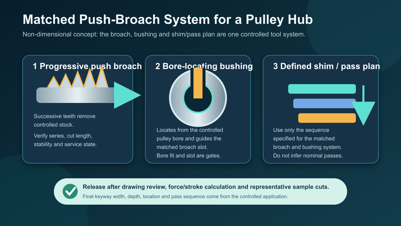
Non-dimensional engineering diagram of a candidate push-broach system. Broach size, bushing, shim sequence and tooth progression must come from the matched tool specification.
The broach, bushing and shims are one system:
- Broach: successive teeth remove controlled increments until the finishing teeth generate the specified keyway.
- Bushing: locates in the pulley bore and guides the broach slot.
- Shims: may be introduced in a defined sequence for a tool system that requires multiple passes.
Do not mix components only because their nominal labels appear similar. Confirm the broach series, bushing type, bore fit, keyway standard and shim schedule with the tool documentation.
The guide slot should be clean and undamaged. The broach must enter square to the bore axis and receive the intended support. If the tool begins at an angle, adding press force will not correct the geometry; it can increase side loading and breakage risk.
BroachingMach’s keyway broach range is a commercial starting point for an application review. Final tooth geometry, material, coating, bushing and regrind plan depend on the pulley drawing and process.
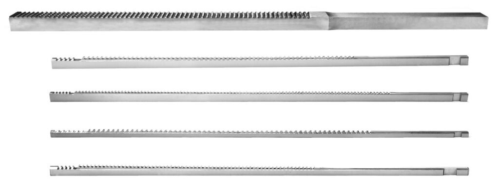
BroachingMach product photo of keyway broaches. It is representative tooling, not a pulley-specific project or a record of achieved keyway accuracy.
Close the Cutting-Force Path Through the Hub and Fixture
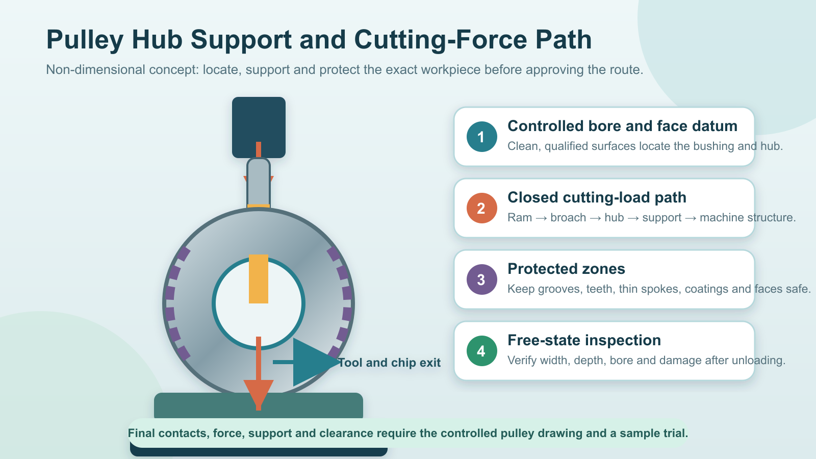
Non-dimensional engineering diagram of the candidate load path, datum, support, protected surfaces and chip exit. Final contact areas require the controlled pulley drawing.
A fixture description should say more than “use a support plate.” The cutting load must pass through:
- the press ram or tool interface;
- the broach;
- the cutting teeth and pulley hub;
- the approved reaction surface;
- the fixture or support;
- the machine table and structure.
The support should carry the load without tilting the bore or concentrating force on a fragile flange. It should not contact pulley grooves, finished teeth, thin spokes or a cosmetic face unless that contact is approved and protected.
The fixture also needs:
- clearance for the broach and chips to exit;
- access for cleaning without reaching into an energized setup;
- control against rocking or rotation;
- repeatable seating on the defined face or hub zone;
- enough open area to avoid trapping the tool below the part;
- a loading method that prevents part/tool mix-up.
The final support geometry should be checked with the part in its free state after unloading. A feature that appears acceptable while the hub is clamped can move when the force is released.
Choose the Machine Route From the Application
Arbor or hydraulic press with a push broach
This can suit a compatible short through keyway, controlled volume and validated load/stroke envelope. Alignment, daylight, support and tool stability are gates. “The press can move the broach” is not the same as a capable production process.
Dedicated keyway or internal broaching machine
Longer cuts, higher volume, controlled tool return, part handling or traceability may justify dedicated equipment. A pull broach can reduce push-buckling risk, but it requires the correct pull end, tool length, stroke, fixture and retrieval architecture.
The push-versus-pull broaching comparison explains this machine/tool distinction. BroachingMach also offers a keyway broaching machine for applications that need more than a standalone press decision.
CNC single-point or keyseating route
A CNC or keyseater route may be considered when flexibility, low volume, blind geometry, tool access or part family makes a long progressive broach unsuitable. The Macchina brocciatrice CNC per scanalature is one candidate category, not a universal replacement for a push or pull broach.
Selection should be based on feature access, production stage, force, stroke, changeover, inspection and total process stability—not on the machine label alone.
Control Chips, Lubrication and Tool Condition
The cutting fluid must suit the pulley material, broach material/coating and site requirements. It should reach the active cutting region rather than merely wet the top of the workpiece.
Observe:
- chip shape and whether chips clear the bushing and exit;
- pickup or smearing on tooth faces;
- scoring, tearing or burr changes on the keyway;
- abnormal force, noise or interrupted motion;
- wear, chipping or damage to guide and finishing teeth;
- contamination or damage on the bore and bushing.
Packed chips and misalignment can turn a normal load trend into tool damage. Do not set a universal number of pulleys between inspections or resharpening. Establish removal criteria from the matched tool, material, load trend and feature measurements.
For a broader make/buy and maintenance decision, see bringing keyway broaching in-house.
Inspect the Keyway as a Feature System
The customer drawing and keyway standard determine inspection. A practical plan may include:
- keyway width;
- keyway depth from the specified reference;
- relation to the bore centerline and approved face datum;
- bore size and roundness after broaching;
- burr, breakout and surface condition;
- damage to grooves, spokes, teeth, coatings or faces;
- fit with the specified key or gauge, when required;
- repeatability after unloading and reloading.
Do not replace these controls with a single statement such as “high precision.” Width, depth, location, bore condition and adjacent-surface protection are separate acceptance items.
First-article validation should use representative material and the controlled production route. Correlate the shop measurement to the customer gauge or drawing method, then record tool ID, bushing, shim/pass state, machine/fixture and material lot.
Sample-Test and Production-Release Plan
Before releasing the process:
- Freeze the drawing revision, material and manufacturing stage.
- Inspect the bore, faces, hub wall and protected zones.
- Confirm the matched broach, bushing and shim sequence.
- Calculate force and verify stroke, daylight and alignment.
- Qualify the support, load path and chip exit.
- Cut representative normal and worst-case parts.
- Record force/load behavior, chips and tool condition.
- Inspect width, depth, datum relationship, bore and protected surfaces.
- Repeat the setup to test reload consistency.
- Define stop, inspection and service triggers.
Sample success, machine acceptance and stable production are different gates. One pulley passing through the broach proves neither long-term capability nor tool life.
Information Needed for a Pulley Keyway Broaching Proposal
Provide:
- pulley drawing and CAD model;
- material, condition and hardness range;
- bore diameter, length, tolerance and finish;
- keyway standard, width, depth, tolerance and datum;
- hub OD, wall, spokes, grooves and protected surfaces;
- production stage and remaining heat treatment/coating;
- annual volume, batch size and takt requirement;
- available press or machine force, stroke, daylight and interface;
- current bushing, broach, fluid and inspection method;
- representative normal and worst-case pulley samples.
These inputs allow BroachingMach to evaluate the candidate broach, bushing, machine, support, chip-control and inspection route. Final tooling, force, stroke, passes, cycle time, capability and tool-life expectations require drawing review, calculation and sample broaching.
Domande frequenti
Can every pulley keyway be push broached?
No. A suitable through bore, cutting length, force/stroke envelope, broach stability, support and tool/chip exit are required. Blind or obstructed features need another route.
Does the bushing determine the keyway depth?
The bushing guides the matched broach, and some systems use a specified shim sequence. The final width, depth and location come from the complete tool system and drawing—not from a generic bushing choice.
Can a hydraulic press broach a pulley keyway?
It may be a candidate if calculated force, stroke, daylight, alignment, support and safety controls are validated. Nominal press tonnage alone is not approval.
When should a pull broach or dedicated machine be considered?
Review it for longer cuts, higher volume, push-buckling risk, controlled handling, tool return or automation. The final route depends on the complete part family and production target.
What if the pulley has a blind keyway?
A conventional through push broach cannot simply be treated as a blind-keyway solution. Relief, chip space, stop position and retraction must be designed for a validated CNC, keyseating or other process.
Final Recommendation
Pulley hub keyway broaching should begin with the workpiece, not the press. Freeze the through bore, keyway drawing, material, hub support, protected surfaces and production stage; then match the broach, bushing, machine and inspection plan.
Send BroachingMach the controlled drawing, material condition, volume, available equipment and representative samples through the contact page. The deliverable should be a validated route and sample plan—not a universal promise that one broach and press fit every pulley.


