On a conventional keyway broaching machine, the cutting is already excellent: one stroke of a multi-tooth broach finishes the slot to width, depth and position, and part one thousand matches part one. What limits output is everything around the stroke — an operator loading and unloading every part, a setup that eats half a shift, a second keyway that means re-clamping by hand. A CNC keyway broaching machine attacks exactly those limits. The cut stays the same broach-and-bushing process; the control, the positioning axes and the automation around them become programmable.
This article is the companion to our keyway broaching machine guide, which maps the full equipment spectrum — vertical, CNC and keyseater — and helps you decide which family fits your parts. Here we go the other way: straight down into the CNC variant’s three depths — how far automation can climb from manual load to a linked line, how quick-change tooling and part programs compress changeover, and what it takes to drop the machine into an existing cell. If you are new to the cutting process itself, the keyway broaching process guide covers tooth-by-tooth chip formation and broach design.
What Is a CNC Keyway Broaching Machine?
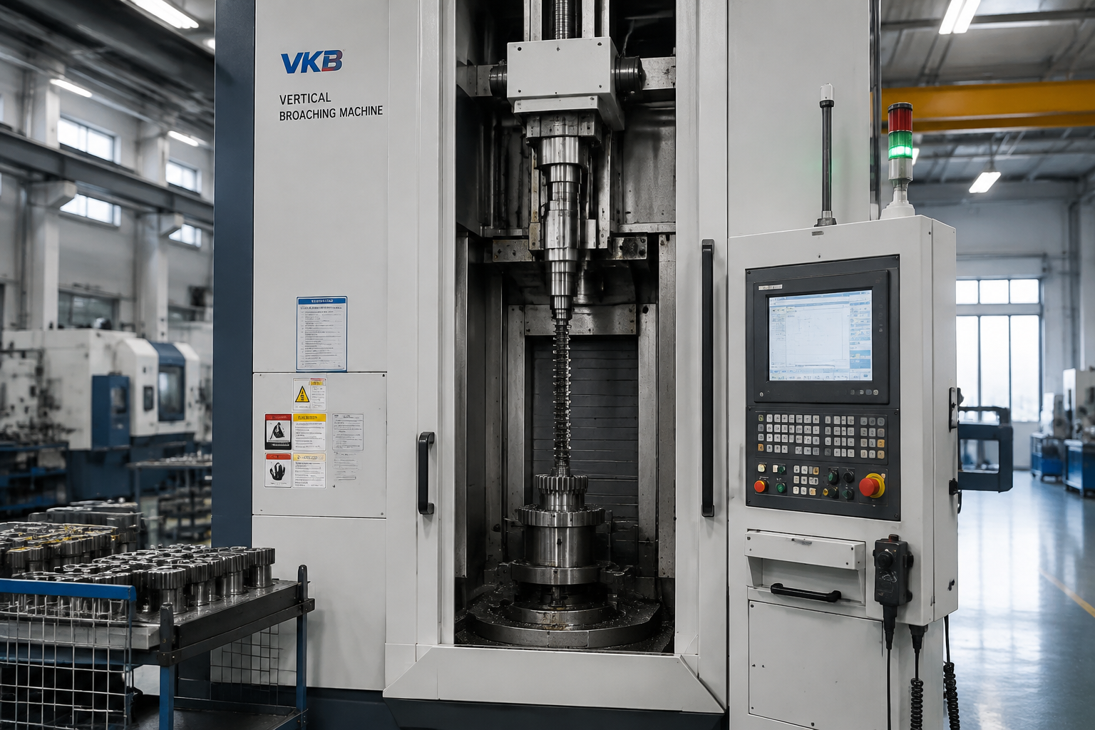
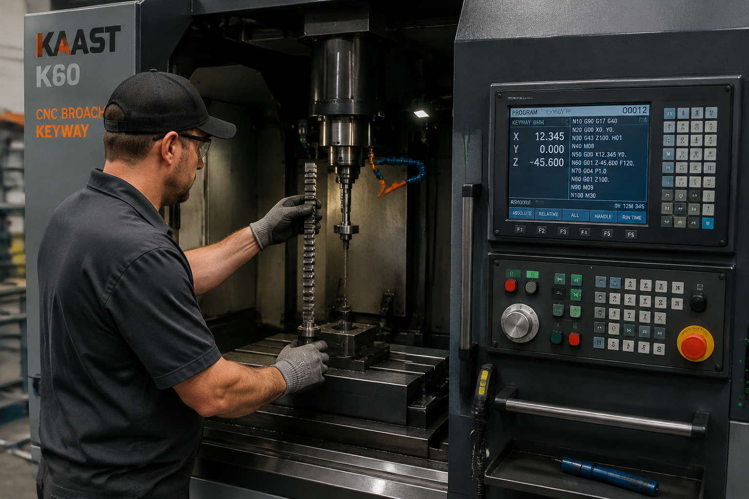
A CNC keyway broaching machine is a keyway production unit built around a numerically controlled ram and a programmable work zone. The ram — hydraulic with proportional control, or servo-driven depending on the design — follows a programmed stroke profile: approach, cutting and return speeds and stroke endpoints are part data, not mechanical adjustments. Around that ram sit the options that turn the machine from a fast cutter into a cell: an indexing work table for multiple keyways, automatic broach changing, and part-loading interfaces — from a simple door-and-cycle interlock up to a full robot or gantry handler.
One principle carries over unchanged from the manual machine: the broach still defines the slot. Tooth widths set keyway width, the tooth stack sets depth, the bushing sets position relative to the bore — the machine contributes force, a straight path and, now, programmable precision about when, where and how many times that path is executed. That division of labor matters when planning a CNC purchase: you are not buying a machine that can cut any keyway any size, you are buying one that executes a family of broach-defined operations faster and with fewer hands. The control-level benefits across all broaching types are covered in our CNC broaching machine guide.
What the CNC Control Changes for Keyway Work
The generic case for CNC broaching — repeatability, data collection, recipe management — applies across the whole process and is covered elsewhere. What follows is specific to keyway production, where the control system changes four things that matter on the floor.
Programmed depth and stroke endpoints. On a relay-logic machine, keyway depth is set by physical stops and confirmed by cutting and measuring a trial part. On a CNC machine the working stroke endpoints are part-program values. The broach still carries the tooth stack that reaches final depth, but where the stroke starts, where it ends and how the tool parks at return are stored, editable and logged. Stroke-position changes between similar parts — a longer hub, a different parking point — become parameter edits instead of stop adjustments, and every program carries its own verified values rather than the setup man’s memory.
Indexed multi-keyway cutting. Parts with two keyways 180° apart, or several axial grooves at set angles, are where manual machines lose the most time. A CNC indexing table rotates the part between passes under program control: broach, index, broach again, all within one clamping. The angular position is no longer an operator eyeball or a detent to engage — it is an axis position, repeated every cycle, which is why symmetry between the two slots holds part after part.
Electronic changeover instead of cam and valve setup. Changing parts on an older hydraulic keyway machine means adjusting relief valves, stroke limit switches and mechanical stops, then proving the setup on scrap parts. On a CNC machine the speed-versus-position profile — fast approach, slow cut through the work zone, fast retract — is an electronic curve stored with the part program, and calling a new profile replaces the mechanical adjustments that used to be the hidden half of every changeover.
Tonnage monitoring as a built-in sensor. Because the control watches ram force and position continuously, every stroke produces a load curve — the cheapest process signal in the machine. A chipped or broken tooth shows as a force drop at a repeatable stroke position, a jammed chip or misloaded part shows as a spike, and either one can stop the machine before it scrapes a hundred more parts. We return to this data in the quality section below.
The Automation Ladder: Four Levels of Keyway Production
Automation on a CNC keyway machine is not a yes/no option. It is a ladder, and the correct rung depends on your batch sizes, part geometry and how many hands you can put at the machine. Climb too low and the machine waits all shift; climb too high and you have bought a robot to feed a job that runs twice a month. The four levels below cover the practical range.
Level 1: Operator Loading with Automatic Cycle
The baseline: an operator loads the part onto the fixture/bushing, closes the guard, and presses cycle start; the machine executes broach stroke, return and unload automatically. Virtually every CNC keyway machine works this way out of the crate, and it already removes the fatiguing half of the job — the return stroke and sequence management. It suits batches from dozens up to a few hundred per run, part families that resist bowl feeding, and job shops where one operator tends several machines. Cycle time is governed by hands: load, unload and door time usually exceed the cutting stroke.
Level 2: Bowl Feeders and Magazines
The first true unattended step: parts are bulk-loaded into a vibratory bowl or gravity magazine, and an escapement or pick-and-place transfers them to the fixture one at a time. This level works when the parts are small, rigid and orientation-friendly — pulleys, sprockets, small gears and similar hub shapes that can be sorted and slid down a track. Batches of several thousand and up justify the feeder engineering. The limits are physical: parts that tangle, are heavy, have fragile features, or cannot be oriented reliably in a bowl belong on the next rung.
Level 3: Robots and Gantry Loaders
A robot arm or overhead gantry presents each part to the fixture in a controlled pose and removes it to an output pallet or conveyor. This level handles what bowls cannot: heavy couplings, parts with finished surfaces that must not tumble, families where a gripper change covers several variants, and layouts where one robot serves the keyway machine plus a neighboring operation. Loading collapses to seconds and repeats to a fraction of a millimeter, which tightens bushing engagement every cycle. The economics favor higher-volume families or multi-machine cells — the robot’s cost spreads across the parts per hour it enables and the shifts it runs unattended.
Level 4: Line Integration
The top rung: the keyway operation becomes one station in a linked line, receiving parts from upstream machining (turning, drilling, honing) and passing them downstream (washing, inspection, assembly) via conveyor, pallet shuttle or the same gantry. At this level the machine is specified as a process module: cycle time must match line takt, the control exchanges handshake signals with the line PLC, and error states feed a supervisory system rather than a local stack light. Line integration is justified when keywaying is one step in a continuous part flow — a hub that must never sit in a bin between operations — and it demands matched takt times, poka-yoke part presentation and agreed fault handling between stations.
Two practical notes on climbing the ladder. First, most CNC keyway machines are built with it in mind — standard I/O and interlock signals for a feeder or robot, guarding designed for automatic operation — so Level 1 equipment can often gain Level 2 or 3 capability later without replacing the base machine. Second, fixture design changes character as you climb: a manual fixture can rely on an operator’s eyes, while a fed or robot-loaded fixture must locate the part positively and detect its presence. Our broaching fixture design guide covers the locating and backing principles behind both.
Changeover Economics: Making High-Mix Production Pay
The classic objection to a dedicated keyway machine is variety: “we run forty different hubs.” The CNC machine’s answer is that changeover time, not cutting time, decides whether high-mix work is profitable. If a changeover consumes an hour, small batches drown in setup; if it takes ten minutes, the same order book runs economically. Everything on the machine that was once an adjustment becomes either a quick-change mechanical interface or a program call:
- Broach quick-change holders. The broach drops into a standardized coupling that clamps hydraulically or mechanically in seconds, with repeatable seating so the tool’s datum returns to the same place. Swapping keyway widths within a family stops being a threaded-and-shimmed chore.
- Zero-point fixture location. Bushing plates and part fixtures sit on zero-point pins or pallet receivers instead of bolt-and-indicate. The next fixture drops onto the same datum every time — no re-indicating what the previous setup already proved.
- Program call instead of setup sheet. Stroke endpoints, speeds, index angles, clamp timing and tonnage limits all live in the part program. Changeover becomes: call the program, load the broach and fixture, prove the first part. The tribal knowledge step — which valve to tweak, which stop to nudge — is gone.
The arithmetic is worth doing honestly. On a batch of, say, two hundred parts with a cutting cycle in the seconds-per-part range, an hour-long changeover can exceed the total cutting time of the batch, while a ten-minute changeover shrinks to a rounding error. That is the whole argument for quick-change hardware on a CNC platform — it converts setup hours into capacity, and lets one machine serve a genuinely mixed order book instead of only monolithic part numbers.
Multi-Keyway and Complex Features in One Setup
Keyway work is rarely one slot per part forever. The geometries that show up in real hub families, and how a CNC machine handles them:
Double keyways at 180°. High-torque drives use two opposed keys to balance the load and halve the stress on each side of the hub. On a manual machine the second pass depends on re-clamping or a manually indexed fixture; on a CNC machine the indexing table rotates the part under program control and the second slot is cut without the part leaving its seat. Same clamping means the same datum for both slots, so the 180° relationship and the depth match hold across the batch.
Multiple axial grooves. Parts such as slip fittings and adjustable hubs use several axial slots at set angles around the bore. The cutting sequence is broach, index, broach, index — a loop in the part program with the index angle and slot count as parameters. Adding a third groove to a family is a program edit plus, if the width changes, a broach change — not a new setup philosophy.
Face slots and stepped-bore keyways. Radial slots on a part face can be broached with the part stood on an indexed fixture, slot by slot around the circle. Hubs with stepped bores — a keyway in each diameter — combine two broaches and two bushings in one fixture, with the program sequencing which tool cuts first. In each case the gain is the same: one setup, one program, all features completed before the part is touched again.
Tonnage Monitoring and Quality Data
A broaching machine measures its own health every stroke. Ram force plotted against stroke position produces a curve that is the fingerprint of the cut — rising as teeth engage the work zone, peaking near full engagement, falling as the broach exits. Once a known-good curve is stored, every subsequent part is compared against it. The two failure modes announce themselves clearly: a broken or chipped tooth removes cutting edges from the stack and the curve drops below its band at a repeatable stroke position; a jammed chip, misloaded part or dull tool drives force above the band. Either deviation can trigger an alarm, a stop or a part divert at whatever threshold the process engineer sets.
Beyond guarding against scrap, the stored curves are process records. Because the machine logs force, position and cycle count against each part or batch, engineering sees a broach heading toward a regrind — force creeping up over hundreds of parts — instead of waiting for a dimension to drift. On the dimensional side, keyway quality is dominated by symmetry about the bore center and the width/depth relationships, verified with functional gauges and measurement sampling rather than inferred from the machine. Our inspection guide for internal spline and slot features covers the gauge-versus-analytical decision; the CNC machine’s role is to keep the population between inspections homogeneous enough that sampling is statistically meaningful.
Boundaries: Where a Keyseater or Machining Center Wins
A CNC keyway broaching machine is not the answer to every internal slot. The hard boundary is the through-bore: a broach must pass through, so a blind bore that bottoms before the slot ends cannot be broached conventionally — that work belongs to a keyseater, whose single-point tool strokes and feeds at the bottom of the hole. The economics boundary is volume: a machining center already in the shop can mill a keyway with a slotting or end mill, and for prototypes or a handful of parts a year that is the right use of existing capability. The broaching machine’s case opens when the same feature repeats in volume, because no reciprocating or interpolating process matches a single-stroke broach for seconds per part. The trade-offs — including blind-bore and large-part cases — are compared in our broaching versus keyseating analysis.
Sizing the Cell to Your Part Family
Choosing the automation level is a three-variable match. Batch size sets the rung: short runs and varied parts make Level 1 with disciplined quick-change the honest answer; thousands per release push toward feeders or robots; a continuous part flow justifies Level 4. Part geometry sets the feeding method: small, rigid, orientation-friendly hubs bowl-feed; heavy, delicate or complex parts want a robot’s controlled grip; large workpieces may stay at manual load with a hoist for good reason. Variety count sets the tooling strategy: the more part numbers share the machine, the more quick-change hardware and the program library earn their cost, and the more sense it makes to standardize bore families so broaches and bushings overlap across parts.
Plan the ladder, not just the rung you need today: specifying the machine with the I/O, guarding and interfaces for automatic feeding costs little at purchase and is the difference between adding a feeder later and buying a second machine. Our CNC keyway broaching machine page lists the machine’s application scope — internal keyways, splines and inner-hole features — and the configurable control and handling options; for the broader machine families and the vertical-versus-CNC comparison, the keyway broaching machine guide and the keyway broaching machine product page carry the rest.
Frequently Asked Questions
When does a CNC keyway broaching machine beat a standard vertical?
When your constraint has moved off the cut itself. If output is limited by operator loading, changeover frequency, multi-keyway indexing or the lack of process data — not stroke speed — the CNC platform addresses those directly. A single high-volume part with one keyway, run for weeks at a time, is well served by a standard machine; mixed families, multiple slots per part or unattended ambitions are the CNC machine’s ground.
Can the CNC control cut different keyway widths without changing the broach?
No. Keyway width and depth are ground into the broach — the control executes the cut, it does not redefine the tool’s geometry. What the control removes is everything around the tool: stroke values, speeds, index angles and clamp sequence are program calls, so changing between broaches is a quick-change holder swap plus a program call instead of a full setup. Different widths still mean different broaches; they just no longer mean lost hours.
Can automation be added to the machine later?
In most cases, yes, if the machine was specified with it in mind. The control architecture, safety circuit and I/O reserved for a feeder or robot handshake are what make a later upgrade a bolt-on project rather than a rebuild. Order those interfaces even if day one is manual loading — the incremental cost at purchase is small compared to retrofitting them.
How does the machine cut two keyways 180° apart?
The part stays clamped in one fixture on an indexing work table. The program runs the first broach pass, commands the table to rotate 180°, then runs the second pass — same broach, same bushing datum, same clamping. Because both slots are cut from one setup, their angular relationship and depth match repeat across the batch without operator-dependent re-positioning.
From Standalone Machine to Production Cell
A CNC keyway broaching machine keeps the part of broaching that already works — the single-stroke, tool-defined cut — and rebuilds everything around it as data: stroke profiles, index angles, load curves, part programs. The payoff scales with how far you take it: quicker changeovers make mixed production profitable, indexing makes multi-slot parts simple, feeding makes shifts unattended, integration makes the keyway one seamless step in the part’s flow.
Deciding which level fits your parts is an engineering conversation, not a catalog click. Send us your part prints, annual volumes and the mix of keyway geometries you run — our engineers will map them to the machine configuration, tooling package and automation level that fits, with the cycle times and changeover picture you can expect. Start with the configuration details on our CNC keyway broaching machine page.