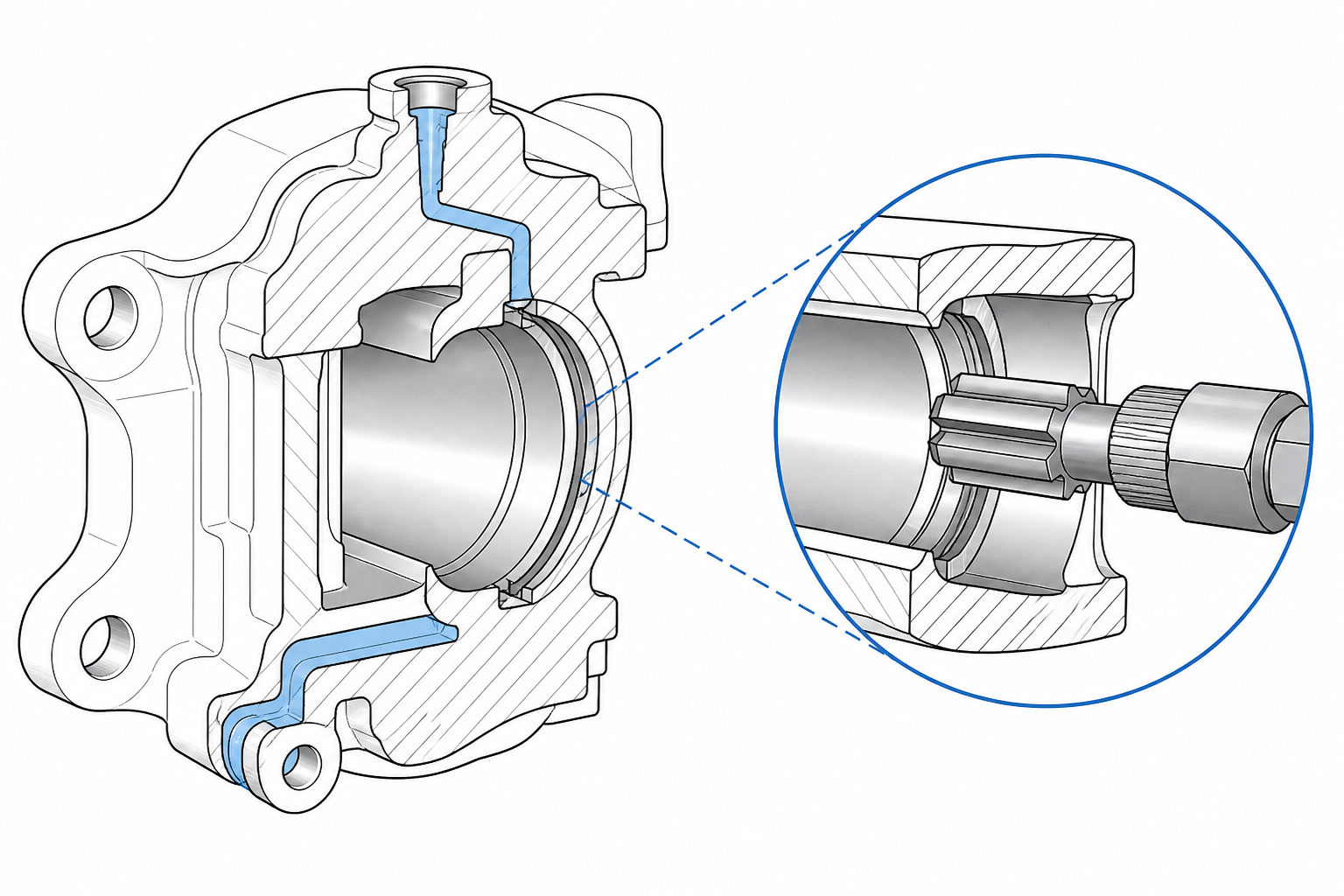
The brake caliper turns hydraulic pressure into clamping force: fluid acts on pistons inside the caliper body, and the pistons press the friction pads against the disc. Every machined feature on the part — the piston bores, the bridge, the fluid passages, the mounting interfaces — exists to keep that force path stiff, sealed, and repeatable over years of thermal cycling. It is a safety component machined to automotive volume, so the process chain behind it is engineered to the last micron and the last second of cycle time.
That process chain is dominated by boring, turning, milling, and drilling. So a fair question from any brake-system engineer is: what does broaching have to do with a brake caliper? The honest answer is that broaching is a targeted tool, not a general one. The piston bores belong to boring and honing, the threaded bleed and fluid ports to drilling and tapping, and nobody proposes broaching as a substitute for any of that. What broaching earns on a caliper program are the formed features — grooves, slots, flats, and shaped surfaces that repeat identically on every part — where a single-pass tool that holds its form over thousands of cycles beats a multi-pass operation on consistency and cycle time.
Which features those are depends on caliper generation and design intent, so this article works with a candidates framework rather than absolute claims. We walk the part anatomy first, then go feature by feature through internal grooves, port and cavity details, and external surfaces; then cover the two disciplines that make or break caliper broaching — cutting cast material and fixturing thin castings — and close with cycle time and machine selection. It follows the same workpiece-case format as our guides on steering wheel hub internal spline broaching and connecting rod broaching.
Brake Caliper Anatomy for Process Planning
Floating vs. Fixed Calipers
Two caliper architectures dominate vehicle brakes. A floating caliper (sliding caliper) has pistons on one side only; the body slides on guide pins, and the reaction force clamps the inboard pad. Its housing is a relatively open casting with a single piston-bore row, guide-pin bores, and a bracket carrying the braking reaction loads. A fixed caliper has pistons on both sides in a rigid body bolted to an upright or knuckle; the body spans the disc like a bridge, carries opposed piston bores drilled through it, and internal fluid crossovers connect the two sides.
For process planning: fixed calipers bring more internal passages and features that must relate precisely to the piston-bore axis; floating calipers add guide-pin bores and bracket interfaces with their own tolerance chains. Both are castings at heart — typically ductile cast iron or cast aluminum — and both arrive at the machining line as near-net-shape parts with a hard skin and a few millimeters of allowance on functional surfaces.
The Machined Features That Matter
Strip a caliper program down to its operation list and the recurring features are:
- Piston bores (cylinder cavities). The heart of the part. Drilled or cored, then rough and finish bored; on many designs honed or roller-burnished to a seal-worthy surface. Grooves in the bore wall locate the piston seal and often a dust boot at the outer end.
- Fluid passages and ports. The inlet port with its threaded fitting seat, internal crossover drillings on fixed calipers, and the bleed screw boss and bore that purge air at the highest point.
- The bridge and window. The material spanning the disc on a fixed caliper, often with a weight-saving window or pocket machined through or into it.
- Mounting interfaces. Bolt-hole patterns, pin bores, and machined pads or ears that locate the caliper on the knuckle or bracket — the features that set pad-to-disc alignment.
- Pad abutment and retention features. Slots, steps, and clip seats that position the pads and carry braking reaction torque.
Almost all of this is turned, bored, milled, drilled, and tapped. The question for a broaching supplier is which items on that list are formed features that repeat at volume.
Which Caliper Features Are Realistic Broaching Candidates
The features on caliper-type castings that can be broached fall into a short list — deliberately framed as candidates, not a claim that every caliper design includes them:
- Grooves inside the piston bore. Where a design calls for a machined groove in the bore wall — seal retention, piston stop, or fluid-return features — a groove of defined width and form is the textbook internal broaching application. The bore is brought to semi-finish by boring first; the broach then pilots in that bore and cuts the groove in one pass, with form and position held in the tool itself.
- Port and cavity details at fluid interfaces. Counterbores, seats, and shaped recesses at the inlet and bleed interfaces — where a fitting must seal against a machined form — are form features a broach produces consistently where volumes justify a dedicated tool.
- External shaped surfaces. Weight-reduction pockets, pad-abutment slots and steps, machined mounting pads, and any defined-width slot with a tight side-to-side relationship are surface-broaching candidates: one stroke produces the complete contour instead of a milled pass sequence.
Just as important is what is not broached. Final piston bore size and surface are boring-and-honing territory; the bleed screw bore and inlet fitting thread are drilled and tapped; guide-pin bores on floating calipers are drilled, bored, and reamed or honed. A sourcing engineer evaluating a “caliper broaching” scope should read it as formed features on a caliper casting — never as a proposal to replace the bore-and-hone backbone of the line.
Broaching Castings: Skin, Hard Spots and Interrupted Cuts
Calipers are castings, and casting changes the cutting problem. Ductile iron bodies bring a cast skin with scale, silica inclusions, and local hard spots — thin chilled regions where the melt cooled against the mold and runs harder than the core. Cast aluminum brings its own version: oxide skins, porosity that opens mid-cut, and Si-phase particles that abrade the cutting edge. In both materials the first teeth into the work can meet hardness the finishing teeth never touch.
Three tooling disciplines manage this. Tooth rise strategy: where the cut enters cast skin, the broach takes a heavier, tougher roughing geometry at the front — enough rise per tooth to get under the skin and cut beneath it rather than scrape along it — then steps down to fine rises for the finishing teeth. Edge preparation: cast iron wants a slightly honed, robust edge; aluminum wants a sharp, polished rake with generous chip-room gullets so the soft chip clears instead of welding to the face. Tooth pitch: whenever a broach crosses a window, port, or porosity, some teeth are momentarily out of the material while others are in, and the pitch must keep at least two or three teeth engaged.
On the machine side, interrupted cutting shows up as force fluctuation within the stroke, and rigid broach guidance keeps the form from deflecting as the load varies. Coolant strategy differs by material: cast irons are often broached dry or with flood oil, while aluminum runs with generous lubricity to protect the sharp edges the finish depends on. The broader material-by-material picture is covered in what materials can be broached.
Internal Grooves in the Piston Bore: Turn, Bore or Broach?
Grooves in the piston bore wall are the most classic broaching candidate on the part — and also where competing processes are strongest, so the choice deserves an honest comparison.
The default route is single-point machining on the same equipment that makes the bore: a grooving tool plunges radially to cut the seal or return groove in line with the boring operation. At low volumes, or where the groove sits near an open bore end with generous tool access, this is usually the right answer — no new machine, no dedicated tool, full flexibility.
Broaching competes on three specific grounds. Multi-feature forms: where a design stacks several grooves, or a groove plus a chamfer plus a relief in a defined axial relationship, an internal broach produces all of it in one pass with the relationships ground into the tool — no accumulated index error. Consistency at volume: the groove form lives in the tool, so part-to-part variation tracks tool wear, which is slow and directional, rather than machine kinematics and insert changeovers. Cycle time: one stroke replaces a sequence of plunge-and-retract moves, which matters when the line is balanced to seconds. And grooves deep in a bore, or profiles a single-point tool cannot reach with adequate overhang, are natural broach work because the broach enters along the bore axis it just piloted on.
The sequencing rule mirrors internal spline broaching everywhere: semi-finish the bore first, let the broach pilot on it, and tool guidance does the alignment work. Where volumes do not justify a dedicated broach, the single-point route stays the honest recommendation; the break-even is calculable once feature geometry and annual quantities are on the table.
Surface Broaching Caliper External Features
The external side of the caliper is where surface broaching earns its place. Weight-reduction pockets in the bridge and body, machined mounting pads, pad-abutment steps and slots, and flat reference faces are all contours a surface broach can sweep in one stroke. Instead of a milling routine — multiple passes, corner-to-corner tool paths, a finish that varies with insert wear — the broach passes once and the complete surface arrives as ground into the tool, corners and radii included.
On a casting this is attractive because the broach can be designed to level the casting’s variation: roughing teeth take the worst of the skin and stock distribution, finishing teeth bring the surface to size. The machine architecture is the classic slab or contour surface broacher, explained in what a surface broaching machine is. For caliper-type parts the practical fit is a surface machine with a fixture plate presenting the casting at the correct height and orientation, often staging multiple parts per stroke.
Two cautions apply. Surface features must be referenced to the same datum scheme as the machined bores — a beautifully broached mounting pad means nothing if it drifts from the bore axis — so the fixture, not the casting skin, carries the location. And interrupted contours (a pocket breaking through into the window, an abutment step ending mid-face) put the tooth-pitch requirement back in play: enough teeth in cut at all times, or the surface will chatter where the interruptions are.
Fixturing a Casting Without Distorting It
A caliper body is a thin-walled casting — stiff in the load path, compliant when clamped carelessly. Broaching pushes significant cutting force through the part, so the fixture is not an accessory; it is half the process. Three rules cover it.
Datum discipline. Cast calipers arrive with casting datums — pads, bosses, or locating holes. The line’s first operations establish machined datums from those, and every downstream operation, broaching included, locates on the same system. The failure mode to avoid is a broach cut referenced to the raw skin: every casting’s skin sits slightly differently, and the broached feature inherits that scatter.
Support against the cut. Broaching force is directional and large. The fixture must back the part along the cutting-force vector — clamps opposite supported surfaces, nest supports conforming to the casting’s ribs and bosses, a scheme that closes the force loop through stiff material. A clamp over a window or thin web, with air beneath it, bell-mouths the casting; the broach cuts the feature true to the deflected part, and it springs out of position when the clamps release.
Low clamping force, spread wide. The clamps’ job is mainly to keep the casting seated — not to crush it. Contact patches spread over ribs, swing or edge clamps that avoid bridge spans, and fixtures that clamp on surfaces machined in the same setup all push distortion out of the equation. For cast aluminum the concern is doubled: the material is more compliant and notch-sensitive, and a clamp mark that iron would shrug off becomes a stress riser or a leak path on a hydraulic part.
Cycle Time, Automation and Line Integration
Caliper production is automotive-volume production, and a broaching operation that cannot hold the line’s rate is a bottleneck regardless of how well it cuts. The planning logic is straightforward: the station’s effective cycle — cut stroke, return, part exchange — must sit inside the takt of the operations around it, with margin for the worst case.
The standard answers, in ascending order of investment: multiple parts per stroke, with a fixture bar staging several castings so one stroke serves multiple parts; shuttle tables or dual-station fixtures, where an operator or robot loads one station while the machine cuts the other, hiding part exchange inside the cut time; and full automation, with a robot tending the broacher as one cell in a transfer or CNC line. Because the broached features are gauged features on a safety component, automated cells usually integrate in-process gauging — air or electronic plugs for grooves, proximity or vision for surfaces — feeding back adjustment or tool-change timing.
Tool management belongs in the same conversation: the reconditioning schedule, and the drift the teeth accumulate between sharpenings, must be part of the control plan from day one. Machine selection ties it all together — stroke, force class, tool guidance, and automation interface decided against the actual feature set and volumes, a decision process laid out in how to choose the right broaching machine.
The Brake Caliper Broaching Machine
When the feature list and volumes point to broaching, the machine follows the features. Internal groove work in piston bores points to vertical internal broaching machines — the part fixtures on the table, the broach enters along the bore axis, a short stroke finishes the feature. External contour and pocket work points to surface broaching machines. Caliper lines frequently end up with a special-purpose configuration: a station engineered around the specific casting, with fixture and automation matched to the line it serves.
That is the configuration behind our brake caliper broaching machine. It is built for this workpiece family: cast caliper bodies with formed internal and external features that must repeat identically across production volumes, on a platform designed to be fixtured for the specific casting and integrated with the customer’s part logistics. That page walks through the configuration logic in detail, and our engineering team scopes fixture and tooling against your drawings.
Related Workpiece Case Studies
Calipers belong to a family of chassis and powertrain components where the same broaching logic — formed features, cast or forged blanks, automotive volumes — repeats across parts. The closest companion case on this site is steering wheel hub internal spline broaching, which covers the internal-form discipline: how the blank prepares the bore, how the broach pilots, and how tolerances and inspection are managed at production volumes. The connecting rod case covers the formed-groove and machined-joint logic. The common thread is the selection criterion: broaching is the process you specify when a formed feature repeats at volume and its consistency is a function of the part — and on brake components that criterion is met more often than a first look suggests.
Frequently Asked Questions
Can you broach a brake caliper?
Not the part as a whole — specific features on it. Piston bores, threads, and precision bores stay with boring, honing, drilling, and tapping. What can be broached are formed features: grooves in the bore wall, shaped recesses and seats at fluid port interfaces, and external contours such as weight-reduction pockets, abutment steps, and formed mounting surfaces. Whether broaching is right for a given feature depends on design and volumes — “candidates evaluated feature by feature,” not a universal claim about all calipers.
What caliper features are better turned or milled than broached?
Single grooves with open tool access at low-to-medium volumes, where a single-point grooving tool on the existing boring equipment does the job with no dedicated tooling. Prototype and short-run work of every kind, where milling flexibility beats broach dedication. And anything whose tolerance is about roundness, size, and surface in a bore — final bore finishing belongs to boring and honing, full stop. Broaching takes over when multiple formed elements must relate precisely, when volumes amortize a dedicated tool, and when cycle time binds.
Is broaching practical on castings with hard skin and inclusions?
Yes, with tooling designed for it. Ductile iron and cast aluminum are both established broaching materials across automotive component families. The tool handles the casting reality: tougher roughing teeth that cut beneath the skin, honed edges for iron and sharp polished edges for aluminum, chip gullets sized to the material, and pitch chosen so interruptions never leave too few teeth in cut. The machine needs rigid tool guidance to ride out the force fluctuation of interrupted cuts, and casting variation is managed by the fixture and datum scheme.
What type of machine is used for brake caliper broaching?
Internal features point to vertical internal broaching machines, where the broach pilots in the semi-finished bore and cuts the groove or form in one stroke. External contours point to surface broaching machines. At automotive volumes the typical configuration is a dedicated or special-purpose station — often our brake caliper broaching machine platform — engineered with casting-specific fixturing and integrated with the line’s automation, gauging, and tool management. Correct sizing follows the actual feature geometry and volumes, which is why we scope machines against part drawings.
If you are machining brake calipers — or quoting a caliper program — and have formed features on the drawings that repeat at volume, that is precisely the work we engineer around. Send the part drawings, material specification, and annual volumes, and we will return a machine, fixture, and tooling configuration with stroke and cycle time worked out against your part. Start with the brake caliper broaching machine page or the broaching machine overview, or contact our engineering team directly with your workpiece details.