
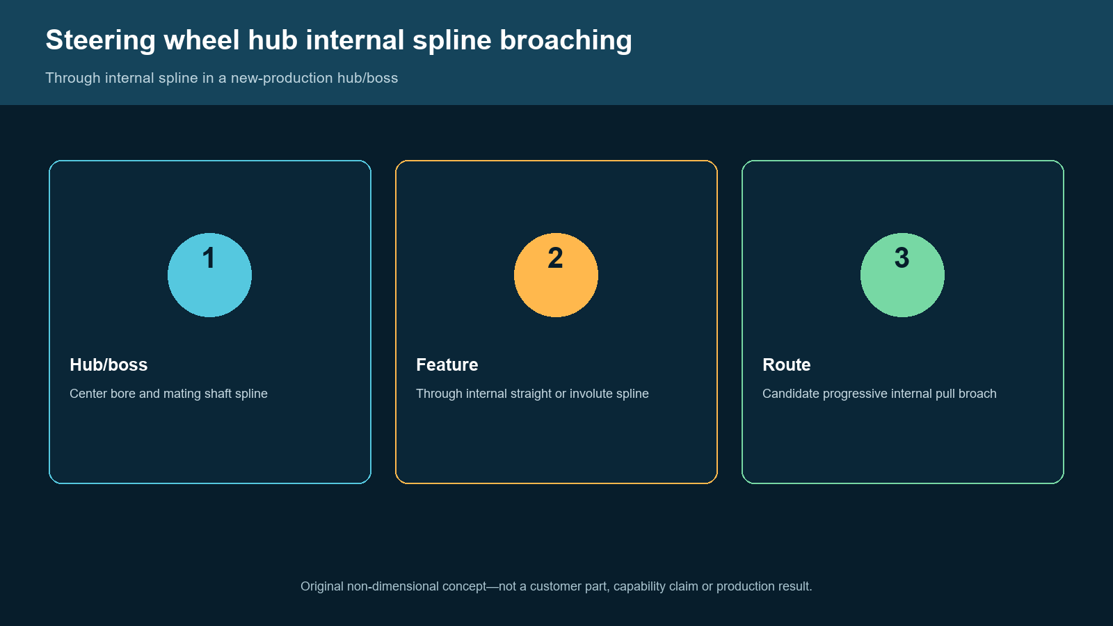
Engineering concept illustration. It is not a customer part, delivered machine or verified BroachingMach project. Final tooling and workholding require drawing review and sample broaching.
A steering wheel hub, also called a steering wheel boss, connects the wheel body to the steering-column shaft. This guide addresses one exact manufacturing task: producing a through internal spline in the center of a new-production steering wheel hub. It does not cover the shaft's external spline, a steering yoke, quick-release product fitment or repair of a used wheel.
The candidate route is a progressive internal pull broach on a vertical pull machine. That route is conditional, not automatic. The spline drawing, pre-bore, material and heat-treatment state, available tool exit, wheel envelope, support strategy and inspection method must all agree before the tool and machine can be selected. This is a Tier C engineering framework with conditional Tier B proposal language; it contains no claimed production result.
1. Define the Exact Steering Wheel Workpiece and Feature
The workpiece is not simply “a steering part.” It is the hub or boss at the wheel center, either integrated into the wheel structure or handled as a controlled subcomponent during manufacturing. The feature is an internal straight-sided or involute spline in the central bore. It mates with an external spline on the steering-column shaft to transfer driver input.
The spline described here must have through access: the broach and chips need a verified exit below the feature. A blind spline, a helical spline and an external shaft spline require different process reviews. The broader internal spline application overview is useful for context, while the spline broaching guide explains general terminology. Neither replaces the controlled steering-wheel drawing.
| Item | Current concept | Evidence status | Required project input |
|---|---|---|---|
| Workpiece | Steering wheel hub/boss | Industry-supported | Part family, construction and variants |
| Feature | Center through internal spline | Product-Page and industry indication | Standard, tooth form, fit and dimensions |
| Mating part | Steering-column shaft external spline | Functional context only | Actual mating-spline data |
| Material condition | Not frozen | Unknown | Grade, condition, coating and certificate |
| Production route | New manufacture | Scope decision | Preceding and following operations |
| Volume | Not assumed | Unknown | Annual/shift mix and changeover need |
2. Freeze the Manufacturing Stage Before Choosing a Broach
Broaching cannot be designed in isolation from the routing sheet. A candidate soft-broaching route starts with a semi-finished hub whose central hole has already been drilled, bored or otherwise prepared. The hub face and bore used for location must be stable enough for the agreed datum strategy, and the broach must remove only the controlled stock defined by the tool design.
If the part is broached before heat treatment, the proposal must address how later heat treatment may change the spline and datum relationship. If a small correction is requested after heat treatment, that is a separate hard-broaching evaluation; it is not permission to remove the full soft-machining allowance with a hard broach. Material hardness, allowance distribution and surface condition must be measured rather than guessed.
Assembly, molding, coating, trimming or installation of decorative parts may also affect the stage. Finished spokes, rim surfaces, electrical interfaces and cosmetic trim can become protected zones. Whenever possible, the process sequence should avoid exposing completed sensitive features to clamping, chips and cutting fluid.
Repair intent is outside this article. Enlarging a used hub, changing its tooth count or adapting it to another shaft introduces unknown wear, damage, material history and fit. A new-production proposal based on controlled blanks must not be presented as a repair instruction.
3. Define Spline Geometry, Datum and Inspection Together
“Spline accuracy” is too vague for tooling or acceptance. The controlled drawing should identify the spline standard and revision, straight-sided or involute form, tooth count, major and minor diameters, pressure angle where applicable, tooth thickness or space width, lead, runout, length and edge/burr requirements. The fit to the mating shaft must be stated by the customer, not inferred from a catalog wheel.
The datum scheme is equally important. A candidate approach may locate from the hub face and the prepared bore or bore centerline, but only the drawing can establish which surfaces govern the final spline relationship. If the wheel body is not symmetric about the hub, the fixture also needs an angular orientation rule and a controlled anti-rotation reaction.
Inspection must follow the same definition. Depending on the drawing, the plan may use a composite or sector gauge, measurement over pins or span, CMM, dedicated spline/gear metrology, or a combination. A go/no-go result alone may not explain profile, lead or datum error. Conversely, a CMM report is not automatically a substitute for the customer's functional gauge. Gauge ownership, calibration, measurement condition and correlation between customer and supplier must be agreed.
4. Confirm Through Access, Starting Bore and Tool Exit

Non-dimensional engineering diagram. Tooth form, broach length, stock and clearances are illustrative and must not be used for manufacture.
A progressive pull broach needs a continuous path through the prepared bore. Before design begins, verify:
- The broach front pilot can enter the starting bore without forced alignment.
- The spline is truly through, with no hidden shoulder or reduced diameter.
- The pull end and cutting teeth can pass through the fixture and machine interface.
- The wheel, fixture and machine provide enough daylight for loading and the complete tool path.
- Chips have a clear exit and collection route.
- The pre-bore size, roundness, straightness and face relationship are within the broach-design input window.
- Burrs, casting flash, coatings or inserts do not obstruct the guide or exit.
An insufficient exit is a HOLD signal, not a reason to “try a shorter broach.” A blind feature may require a separately validated shaping, keyseating, CNC single-point or other process. The selection must be based on geometry, stock, quality and production needs.
5. Steering-Wheel-Specific Process Difficulties
The large wheel envelope surrounding a relatively small hub changes loading and reaction behavior. The operator or automation must bring the hub to the tool axis without striking the rim, spokes or trim. An off-center mass or asymmetric spoke pattern may create handling and overturning effects even when the spline itself is centered.
The hub can also be thin relative to the cutting load. Concentrated clamping may tilt, mark or distort the part. Supporting only the outer rim is risky because the cutting force must travel from the hub through a less direct structure before reaching the fixture and machine. The candidate fixture should therefore create a short, stable load path near approved hub reaction surfaces while respecting protected zones.
Different wheel families may share a spline designation yet have different envelopes, hub-face heights, spoke clearances, materials or protection requirements. “One tool and fixture fits all” is not a safe assumption. Each variant needs a documented compatibility decision and changeover control.
6. Build the Datum, Fixture and Protected-Zone Map

Non-dimensional engineering diagram. Contact pads, clamp locations and gauge access are candidates only; the approved drawing and sample trial control the final layout.
| Zone | Function | Main risk | Candidate control |
|---|---|---|---|
| Hub face | Primary axial datum and reaction | Dirt, burr or tilt | Clean, qualify and support near the hub |
| Prepared bore | Tool guide/centerline input | Oversize, taper or misalignment | Inspect before loading |
| Approved hub land | Cutting-force reaction | Local deformation or marking | Distributed replaceable support |
| Spokes and rim | Finished or sensitive structure | Clamp marks, impact, distortion | Default protected/no-clamp zone |
| Angular feature | Orientation reference if required | Wheel rotation under cutting load | Positive anti-rotation device |
| Tool exit | Broach and chip passage | Collision or chip packing | Open, verified clearance |
| Gauge access | Post-process inspection | Obstructed or contaminated surface | Clean and inspect free of clamp load |
The cutting-force loop should close from the broach teeth into the hub, through the approved reaction surfaces and fixture body, and into the machine structure. Anti-rotation should react torque at an authorized robust feature; it should not rely on friction against a cosmetic surface. Clamps stabilize the part but must not create a temporary shape that disappears after unloading.
The existing Steering Wheel Broaching Machine product Page describes a vertical pull concept and loading accommodation for a large wheel. It is a relevant architecture lead, not proof that the pictured machine, fixture or published specifications fit every hub.
7. Select the Internal Pull Broach Conditionally
For a straight through internal spline, a progressive pull broach is a candidate because the pull places a long slender tool primarily in tension. The tool may include a pull end, front pilot, roughing teeth, semi-finishing teeth, finishing or sizing teeth, rear pilot and retriever interface. The actual sequence depends on the pre-bore and finished form.
Straight-sided and involute splines are not interchangeable labels. Tool profile, guide strategy, tooth progression, chip space, material, heat treatment and coating must be designed from the drawing and workpiece condition. A helical feature would additionally require controlled relative rotation and is outside the frozen concept.
Die Broach Tools overview shows the broader tooling family, and the broach-holder guide provides interface context. The proposal must still calculate the individual broach and confirm pull-head compatibility. No standard tool life is promised: change and regrind decisions should use edge condition, load trend, chip form, pickup, chipping and measured part drift.
8. Select the Machine and Process Modules
A vertical pull-down or pull-up machine is a candidate because it can align the internal tool path with gravity and support a dedicated loading arrangement. Final architecture depends on calculated cutting force, broach length, working stroke, daylight, rigidity, wheel envelope, loading direction, retriever arrangement and plant layout. The general broaching machine overview can help compare architectures without fixing a model.
The complete solution also needs:
- A pull head, retriever and guide interface matched to the broach.
- A fixture with defined datum, support, clamp, anti-rotation and error-proofing.
- Controlled cutting-fluid delivery compatible with part and tool materials.
- Filtration, chip collection and an unobstructed exit path.
- Part-family identification and recipe/changeover control.
- Guarding and loading access appropriate to the wheel envelope.
- Load/position monitoring used as process evidence, not final dimensional acceptance.
- Traceability fields for part, drawing, tool, fixture, recipe and inspection result.
Fluid selection affects lubrication, cooling, chip transport, staining, corrosion and fire-risk controls. Review the broaching cutting-fluid guide as a starting point, then qualify the fluid against the actual hub material and plant requirements.
9. Run a Closed-Loop Broaching Process
- Identify the workpiece family, drawing revision and approved process route.
- Verify material condition, pre-bore, datum surfaces and hard-reject conditions.
- Inspect the broach, pull end, pilots, guides, retriever and fixture.
- Clean the datum and support surfaces; load the wheel without contacting protected zones.
- Confirm orientation, anti-rotation engagement and open tool/chip exit.
- Apply the qualified cutting fluid and run the controlled stroke.
- Monitor load trend, sound, chips and any unexpected part or fixture movement.
- Complete the verified tool exit and controlled return/retrieval sequence.
- Unload, clean and inspect the part in the specified free condition.
- Inspect the broach for pickup, edge damage and packed chips; route records to OK, NOK or engineering review.
An alarm, abnormal load, damaged edge, unexpected mark or quality shift should trigger the approved stop-and-review route. The broach-breakage prevention guide and Leitfaden zur Fehlerbehebung beim Räumen provide general checks, but the steering-wheel control plan must define the actual response.
10. Control Tool Condition Without a Fixed Life Claim
A tool-life plan starts with a documented baseline for the new or correctly resharpened broach. Record cutting-edge condition, relevant tool dimensions, coating state, pull-end condition and the normal load/chip/part-quality pattern established during an approved trial.
During production, look for correlated change: rising or unstable load, altered chip form, material pickup, edge chipping, burr or surface change, and movement in measured spline characteristics. A single signal may justify inspection, but a fixed part count is not supplied here. Material lots, allowance, fluid condition, alignment and handling can all change wear behavior.
Resharpening must preserve the designed tooth sequence and chip geometry. The tool record should define how much stock remains, which dimensions are restored, whether coating is reapplied, and when the broach is quarantined for engineering review instead of returned to service.
11. Define Sample Test and Acceptance Evidence
The sample plan should include representative normal and worst-case parts from the controlled family. Keep drawing revision, material/heat-treatment record, pre-bore measurements, tool identity, fixture revision, machine recipe and inspection result linked for every sample.
Acceptance should cover:
| Item | Reference method | Required evidence |
|---|---|---|
| Spline form and size | Drawing-defined gauge/metrology | Raw result and instrument identity |
| Datum relationship | Agreed free-state setup | Repeat setup readings |
| Burr and surface | Specified visual/instrument method | Report and controlled photos |
| Protected zones | Approved visual/dimensional check | Before/after evidence |
| Cutting behavior | Machine trace plus observation | Part-linked trial record |
| Repeatability | Agreed sample plan | Part-by-part results |
| Tool condition | Controlled inspection | Before/after record |
A successful sample broach is not automatically FAT, SAT or stable production approval. Each gate needs its own scope and evidence. Final acceptance should not rely only on the machine display or measurements taken while the part is clamped.
12. Information Needed for a Steering Wheel Hub Proposal
Provide the controlled part drawing and CAD model, workpiece family and variants, spline standard and fit, mating-shaft data, material and heat-treatment condition, pre-bore dimensions and stock, datum and inspection method, protected surfaces, wheel envelope and mass distribution, production volume and mix, current route, plant constraints, coolant requirements, and representative normal and worst-case samples.
These inputs allow BroachingMach to evaluate the candidate pull broach, vertical machine architecture, fixture, anti-rotation, chip-control and inspection plan. Final tool geometry, force, stroke, machine configuration, cycle time, accuracy and tool-life expectations can be confirmed only after drawing review, calculation and sample broaching. Submit the controlled inputs through the BroachingMach contact page.
13. Frequently Asked Questions
Does every steering wheel hub use an internal pull broach?
No. The feature must be internal, suitable for broaching and accessible through the part. Blind access, very low volume, uncertain stock, post-heat-treatment correction or special forms may favor another process after review.
Can the finished steering wheel be used as the fixture datum?
Only drawing-approved surfaces should locate and react the cutting load. The rim and spokes may be unsuitable because of compliance, coatings, cosmetics or assembly variation. A candidate layout supports close to the hub while protecting the rest of the wheel.
Should the spline be broached before or after heat treatment?
That depends on material, distortion, allowance and the required final relationship. Soft broaching and small-allowance hard finishing are different tool-and-process decisions; neither can be assumed without the route and sample data.
How is the internal spline inspected?
The drawing may require a functional gauge, sector gauge, measurement over pins/span, CMM or dedicated spline metrology. The customer and supplier should correlate the chosen method and measurement condition before acceptance.
Can one tool and fixture cover every wheel variant?
Only after a compatibility review. Spline data, hub height, wheel envelope, material, protected zones and loading access may change even within one vehicle program. Variants need controlled tooling and changeover decisions.
Schlussfolgerung
A steering wheel hub through-spline can be a strong candidate for internal pull broaching, but the correct solution begins with the exact hub, feature, material state, pre-bore, datum and inspection definition. The wheel envelope makes support, anti-rotation, protected surfaces and chip exit as important as the broach itself.
The safe proposal sequence is therefore: freeze the new-production workpiece and route, verify through access, design the broach from the spline drawing, close the fixture load path near the hub, select the machine from calculated application needs, correlate inspection, and prove the system with controlled samples.
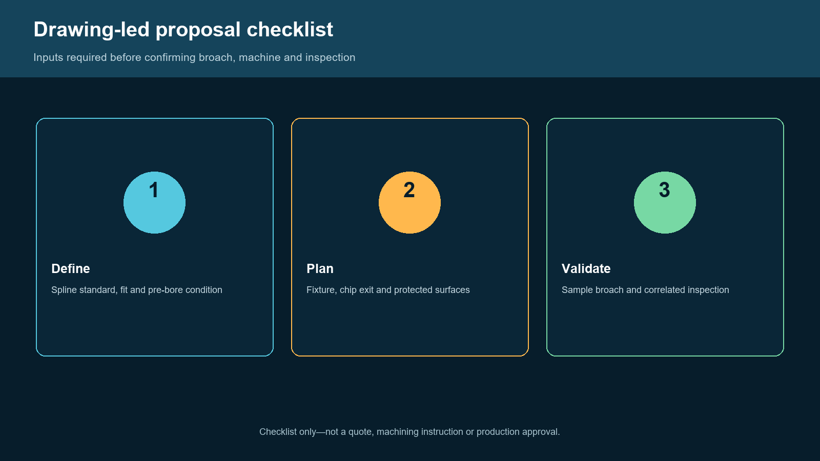
Original non-dimensional engineering concept. It is not a customer part, delivered machine, verified project or production approval.


