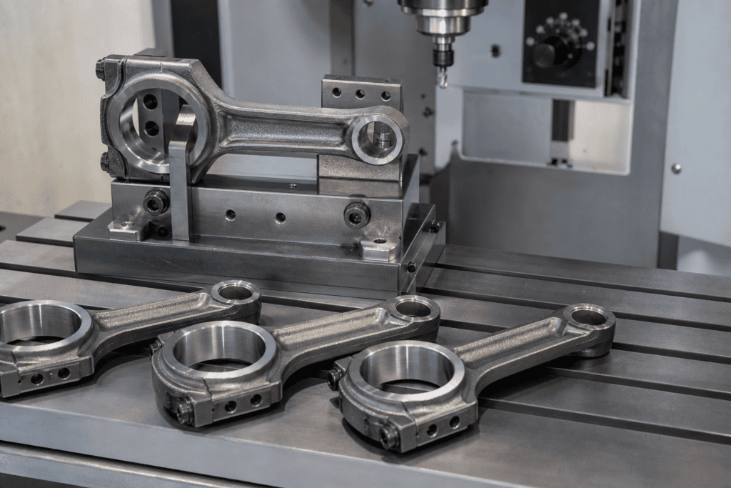

The connecting rod is one of the most heavily loaded parts in an engine. It converts the reciprocating motion of the piston into rotation at the crankshaft, cycling between tension and compression millions of times over its service life. Almost every dimension on the part — the big-end bore, the small-end bore, the distance between them, the bolted joint at the parting line — exists to serve that duty cycle, and the machining process chain reflects it.
That chain is dominated by boring and honing. So when engine supply engineers hear the phrase “connecting rod broaching,” a fair question follows: what is there on a connecting rod to broach at all? The answer is specific. Broaching is not used to make the rod’s round bores — those belong to drilling, boring, and honing. Broaching earns its place on the formed features: locating grooves and keyway-like slots inside the bores, the machined parting-face geometry used on rod-and-cap joints that are not fracture split, and the notching steps that support fracture splitting itself.
This article maps where broaching fits in connecting rod production: which features it cuts, where it sits in the process sequence, how fracture splitting reshaped demand for it, what the tooling demands, how to select the machine, and how broached rod features are inspected. It follows the same workpiece-case format as our guides on turbine disc fir-tree slot broaching and steering wheel hub internal spline broaching.
What Broaching Actually Does on a Connecting Rod
Start with the part itself. A conventional connecting rod has a small end (the piston pin bore), a big end (the crankshaft journal bore, split into the rod body and the cap), two connecting-rod bolts, and an I-beam shank between the bores. Each region carries its own machining operations, and only some are broaching candidates.
The features that are realistically broached on connecting rods fall into a short list:
- Internal locating grooves and keyway-style slots. Some rod designs call for a groove, slot, or flat inside the big-end or small-end bore — to locate a bearing shell, key an insert, or give an oil feature a defined position. Internal grooves in a bore are the textbook broaching application, and rod bores are no exception.
- Machined parting-face geometry. On rods where the body and cap are cut apart and machined rather than fracture split, the joint face often carries a stepped, tongue-and-groove, or serrated form that locates the cap laterally under bolt load. Producing that form accurately on both halves is a classic surface-broaching task — the same family of external broaching used for other machined joint faces.
- Crack-start notches for fracture splitting. Fracture-split rods need a notch at the inner wall of the big-end bore to initiate a controlled crack. Laser notching is the most common method today; mechanical notching with a dedicated cutting tool is an established alternative. Either way, the notch is a small, precise internal feature — the kind of geometry broaching tooling handles well.
Just as important is the list of what is not broached. The big-end and small-end bores themselves are produced by drilling, rough and finish boring, and honing — the roundness, size, and surface finish requirements live in honing territory, not broaching territory. The rod end faces are milled and ground. The bolt holes are drilled and spot-faced, and the bolt head seats are machined with dedicated cutting tools. A shop that expects to buy a broaching machine to make connecting rod bores is specifying the wrong machine — this division of labor comes first.
The Connecting Rod Machining Sequence: Where Broaching Fits
Connecting rods for volume production start as forged steel (or, in many passenger-car programs, powder-forged) blanks, already close to final shape. From there, a typical high-volume sequence runs broadly as follows — ordering varies with part design and whether the rod is fracture split:
- Blank preparation — forging, heat treatment, and shot blasting to establish the material condition and clean the skin.
- End-face machining — milling and fine milling (or grinding) of the two boss faces to create the primary datum for everything that follows.
- Hole generation — drilling and core drilling of the small-end, big-end, and bolt holes.
- Rough and semi-finish boring of both bores, leaving a defined stock allowance for finishing.
- Formed-feature machining — this is where broaching operations slot in: internal grooves and slots in the bores, and on non-fracture-split rods, the parting-face forms on the body and cap.
- Separation and finishing — fracture splitting (with pre-notching) or sawing/machining the cap apart; finish boring and honing of the big-end bore; finish honing of the small-end bore (often with a bushing pressed in beforehand).
- Post-processing — weight and moment balancing with graded material removal where required, washing, assembly of cap to body, and final inspection.
Two sequencing principles matter. First, datum consistency: broached features inside a bore must relate to the same datum system as the bore itself, which is why internal broaching is scheduled after the bore is at least semi-finished — the broach pilots in the bore, so the bore defines the feature’s position. Second, order relative to separation: on machined-joint rods, parting-face broaching happens while cap and body can still be referenced to one another; on fracture-split rods, the notch must come before the split, and post-split bore work must respect the fracture surfaces as the locating interface.
How Fracture Splitting Changed the Broaching Scope
No discussion of connecting rod broaching is honest without fracture splitting in it, because that single process change removed a substantial block of broaching work from passenger-car rod lines.
In the conventional process, the rod body and cap are separated by machining, then bolted back together for bore finishing. For the joint to carry load and locate the cap precisely, the parting faces are machined flat and true, and a positive locating form — serrations, steps, or a tongue-and-groove — is cut into both halves. On high-volume lines those forms were efficiently produced by broaching: one pass per half, a dedicated form broach, repeatable to a few microns, at a cycle time conventional milling could not touch. It worked, but it consumed tooling, floor space, and tolerance stack — every machined interface between body and cap added a source of variation.
Fracture splitting inverted the logic. A notch is placed at defined points on the big-end bore’s inner wall, and a radial expansion tool splits the rod along it in a controlled instant. The fracture surfaces form a unique mating topography — the cap realigns along the crack faces with essentially zero lateral shift, and the joint needs no machined locating forms at all. For the mass-market forged-steel rods that adopted the technology widely, machined-joint broaching operations largely disappeared from the line.
What did not disappear:
- Internal formed features in the bores. Grooves, slots, and flats specified inside the big-end or small-end bore exist independently of how the cap is separated, and they remain broaching work.
- Notching itself, where it is done mechanically. Even where lasers cut the notch, the process step it enables is a fracture — and the equipment that notches, splits, and verifies sits alongside the machining line.
- Rods outside the fracture-split envelope. Larger rods, some diesel and industrial engine rods, and designs in materials or geometries not suited to controlled fracturing still use machined joints — and with them, machined parting-face forms. The practice has not vanished; it has retreated to the segments where it remains the right engineering answer.
The takeaway for a process engineer: connecting rod broaching demand is now concentrated in bore-internal features and surviving machined-joint designs, and any equipment justification should be built around those applications rather than the joint-face volume that fracture splitting took away.
Tooling and Fixturing: Rods and Caps, Matched and Repeatable
Connecting rods are small, thin-walled parts machined in very large volumes, and both facts shape the tooling. The problems specific to rod broaching are parting-face symmetry, bore-referenced position, and cycle time.
Referencing body and cap to one another
On machined-joint rods, the locating form on the cap must mate with the form on the body well enough that the assembled bore runs true after bolting. When body and cap are broached as separate workpieces, the fixture for each must pick up the same datum scheme (typically the bolt holes and end faces) so the two halves agree. Shops handle this with dedicated fixtures per part number and, where volumes justify it, twin-station setups that cut body and cap forms in one cycle on one machine, removing machine-to-machine variation entirely.
Symmetry and true position of bore-internal features
A slot or groove inside the big-end bore is dimensioned against the bore centerline: symmetry about the parting plane and true position relative to the bore are the two controls that decide whether the broached part is good. Because an internal broach pilots in the bore, the bore’s semi-finished condition becomes the positioning authority — which is why the process sequence puts semi-finish boring ahead of broaching. On thin rod sections, the fixture also needs support that keeps clamping distortion from printing into the finished feature; clamping force direction, support placement under the cut zone, and consistent part seating are the difference between a process that holds symmetry and one that scrapes parts.
Multi-part fixturing for cycle time
Rod programs run at automotive volumes, and single-part cycles rarely meet takt on their own. The standard answers are multi-part fixtures — several rods in a row so one stroke cuts the same feature in each — and indexing or shuttle tables that let an operator or robot load one batch while the machine cuts another. Because the features are short, stroke is rarely the constraint; load and unload time is, which is why automation pays for itself faster on rod work than on long-stroke applications.
Choosing the Machine: Vertical Internal, Horizontal, or Special-Purpose
Connecting rod broaching features are short in the stroke direction, which pushes machine selection toward compact vertical internal machines — but the full decision has more branches than that.
- Vertical internal broaching machines are the natural fit for grooves, slots, and notches inside rod bores: the part sits on a table fixture, the broach enters the bore, and a short downward stroke finishes the feature. Footprint is small, part loading is ergonomic, and stroke requirements are modest. Our internal broaching machine guide covers the configuration details.
- Horizontal machines earn their place where stroke or multi-part fixturing demands it — long serrated joint forms or fixture bars carrying many rods in series can favor a horizontal layout even though individual features are short.
- Special-purpose and rotary-transfer machines are the volume answer: purpose-built cells combining broaching stations with load/unload automation, and on fracture-split lines, integrating notching, splitting, and verification into one unit — engineered per part family, and where automotive takt requirements genuinely live.
Tonnage follows from the cut, not the part: feature width and depth, material hardness (heat-treated rod steel is hard on tools and forces), features cut simultaneously, and parts fixtured per stroke together set the force requirement. Because rod features are small but the steel is tough, single-feature tonnage is modest — the design conversation is usually less about force than about stroke, tool guidance, automation interface, and chip management. For a structured walkthrough of matching machine type, tonnage, and stroke to a workpiece, see how to choose the right broaching machine.
Tolerances and Inspection of Broached Rod Features
A broached connecting rod feature carries three families of requirements, and each has its inspection method.
Size — groove width, slot width, notch geometry — is the simplest. Plug and ring gages give a fast functional check at the machine; air gages and snap gages suit higher-volume in-process control where a few microns of drift matter. Because broach teeth wear progressively, size drifts in a known direction over tool life, and a scheduled tool reconditioning cycle keeps the drift inside the band.
Relationship controls — symmetry of a groove about the parting plane, true position of a feature to the bore, squareness of a joint face form — are what make or break the part function. Functional gaging with locating pins and dial indicators is the production-floor answer for symmetry and position on high-volume rod lines; coordinate measuring machines sample the same characteristics at lower frequency and capture full geometry for capability studies. Statistical process control is standard on automotive rod lines, and broached features are tracked like every other characteristic in the control plan.
Surface and edge condition rounds out the scope: finish in the broached groove, burr condition at the feature edges (burrs in an oil groove or at a bearing-locating form are functional defects, not cosmetic ones), and on fracture-split rods, verification of the notch geometry that precedes the split. The general methods for verifying broached workpiece features mirror those in our broach tool inspection overview — the tool is inspected to protect the part, the part to validate the process.
Broaching vs. Milling Connecting Rod Features
Every broached rod feature could, in principle, be milled — a slot can be contour-milled, a serrated joint form can be cut with a form cutter or a plunge-and-index routine. The choice is a volume decision, and it is worth stating both sides honestly.
Milling wins at low volume and high variety. A machining center already on the floor cuts the feature with no dedicated broach tool to purchase and no machine to justify, with full flexibility when the design changes or the shop runs many rod variants at low quantities. For prototypes, aftermarket short runs, and repair work, milling is usually the right call.
Broaching wins at volume and repeatability. One stroke produces the complete form; the geometry lives in the tool, so part-to-part variation tracks tool wear rather than machine kinematics or operator setup; cycle time per part is a small fraction of a milling routine; and the consistency a bolted rod joint or bearing-locating groove needs is exactly what a dedicated broach delivers hour after hour. The trade is tooling dedication: a broach is ground for one feature on one part family, and the break-even sits where volume amortizes the tool against the saved machine time. We compare the two feature by feature in broaching vs. milling for internal keyways and profiles.
Related Broaching Case Studies in Powertrain Components
Connecting rods sit in a broader family of powertrain parts where the same broaching logic applies — internal forms, high volumes, tight relationship tolerances. Two case studies on this site cover the pattern in detail. Steering wheel hub internal spline broaching walks through a classic internal-form application: spline data, tool design, and how the forged blank prepares the bore. Transmission gear internal spline broaching covers the same discipline at gear-production volumes, including tolerance strategy and inspection.
The same reasoning extends across the engine and driveline: crankshaft keyways and Woodruff slots, timing sprocket and pulley bores, and gearbox spline bores are all broached on the argument made feature by feature above — that when a formed internal or joint feature repeats at volume, the process that cuts it in one stroke wins on consistency and cost.
Frequently Asked Questions
Can you broach a connecting rod?
Yes — for specific features, not for the part as a whole. The big-end and small-end bores are produced by drilling, boring, and honing, and broaching does not replace them. What broaching produces are the formed features: internal grooves, slots, and keyway-type forms in the bores, the machined locating forms on rod-and-cap parting faces (on designs that are not fracture split), and mechanically produced crack-start notches on fracture-split rods. A drawing calling for a formed internal feature at production volumes puts broaching on the shortlist.
What type of broaching machine is used for connecting rods?
Short internal features point to compact vertical internal broaching machines, where the rod sits in a fixture and a short stroke finishes the groove or slot. Longer joint-face forms or multi-part fixture bars can favor horizontal machines. At automotive volumes, the typical answer is a special-purpose machine or an integrated cell combining broaching with automation — and, on fracture-split lines, with notching, splitting, and verification stations. Machine choice follows stroke, tool guidance, and automation interface more than raw force.
How much tonnage does connecting rod broaching require?
There is no single number, because the force requirement is set by the cut, not the part: total width and depth of the features, the hardness of the heat-treated steel, the number of parts fixtured per stroke, and the tooth load built into the broach design. Individual rod features are small, so single-part tonnage is modest — but multi-part fixturing and tough material raise it, and the machine should carry margin for tool reconditioning changes over the program’s life. The correct approach is a calculation against the actual feature geometry; our tonnage calculation guide shows the method, and we run the numbers for buyers who send part drawings.
Did fracture splitting eliminate broaching from connecting rod production?
It eliminated a large share of it on passenger-car lines. Fracture splitting replaced the machined body-cap joint — flat parting faces plus broached serrations, steps, or tongue-and-groove forms — with a controlled fracture that needs no machined locating geometry, so those joint broaching operations largely left the line. It did not touch bore-internal features, which are broached the same way regardless of how the cap is separated, and machined joints persist in rod designs outside the fracture-split envelope. The honest summary: fracture splitting concentrated connecting rod broaching into fewer, more specific applications rather than removing it.
If you are machining connecting rods — or quoting a rod program — and need a broaching operation engineered around the actual features on your drawings, that is precisely what we do. Send the part drawings, material condition, and annual volumes, and we will return a machine and tooling configuration with tonnage, stroke, and cycle time worked out. Start with the broaching machine overview, or go straight to contacting our engineering team with your workpiece details.