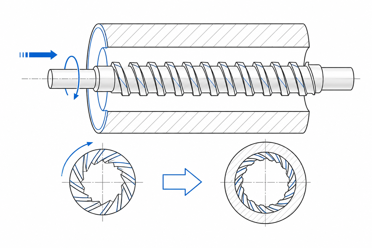
Most internal splines run straight along the bore. Open a modern automatic transmission, an EV reduction gear, or a high-torque coupling, however, and the internal teeth are almost always angled. These helical splines and internal helical gears engage progressively instead of tooth-by-tooth all at once, and producing them in a finished bore is the job of helical broaching — a process that adds a precisely synchronized rotation to the familiar straight cutting stroke of a broach.
This guide walks through how helical broaching works, the three ways it is implemented on the shop floor, what goes into the design of helical broaches, and what the process demands from the machine, the fixture, and the inspection lab. If you need the fundamentals of the process first, start with our primer on what broaching is.
What Is Helical Broaching?
Helical broaching is a machining process in which a broach moves in a straight line through a bore while the broach, the workpiece, or both rotate about the bore axis at the same time. The two motions are rigidly coupled: for every increment of axial travel there is a defined increment of rotation. Each cutting edge therefore sweeps a spiral path and generates an internal helical surface — a helical spline, an internal helical gear, a spiral serration, or a helical keyway form.
Two parameters define any helical form:
- Lead — the axial distance over which the helix completes one full revolution (360°). Lead is set by the mating component and is the invariant of the part.
- Helix angle — the angle between the tooth flank and the bore axis, measured at a stated diameter. It is derived from the lead: tan(β) = πd / L, where d is the pitch diameter and L is the lead. The same lead therefore produces a steeper helix on a large diameter than on a small one.
Because lead is fixed, every helical broaching setup must hold one non-negotiable relationship: a constant ratio of linear travel to rotation. How a shop generates and controls that ratio — electronically, mechanically, or through the broach itself — is the central engineering decision, covered in detail below.
The kinematics are the same as those behind rifling in a gun barrel, where a broach or button tool is pulled through the bore while rotating to lay down spiral grooves. Firearms and transmission gears sit at opposite ends of the size spectrum, but the geometry — linear feed plus controlled twist — is identical.
Helical broaching is a specialized branch of spline work. For the broader picture on tooth forms and broaching strategy, see our complete guide to spline broaching.
How Helical Broaching Differs from Straight Broaching
In conventional internal broaching, the broach has one motion: a straight pull or push through the bore. The teeth sit in straight rows, each row takes its cut, and the resulting splines, keyways, or polygon forms run parallel to the axis. The machine needs force and rigidity, but only along a single axis.
Helical broaching adds a rotational degree of freedom, and that changes nearly everything downstream:
- The rotation must be driven or guided. The twist has to come from a rotary servo axis, a mechanical lead guide, or the helical teeth of the broach itself — it cannot be left to chance.
- Cutting force gains a tangential component. The torque generated at the tool must be reacted by the machine spindle, the guide train, or the fixture, not just axial force into the ram.
- Chip formation changes. Helical teeth slice with a shearing action similar to a helical milling cutter, which generally smooths the cut but alters chip flow and the chip room each gullet must carry.
- Alignment is less forgiving. Squareness between the bore axis and the axis of rotation directly affects how the helix starts and how the flanks form over the length of the part.
None of this makes helical broaching exotic — it is daily production practice in drivetrain plants worldwide — but it does mean the machine, tooling, and fixturing must be specified as a system rather than assembled from general-purpose components.
Why Engineers Specify Helical Internal Forms
Designers accept the added cost of helical forms because the geometry buys real performance. The advantages trace back to one fact: helical teeth engage progressively. Instead of an entire tooth face entering the mesh at once, contact rolls across the flank as the parts rotate, and more than one tooth shares the load at any moment.
The practical consequences:
- Higher load capacity in the same envelope. With multiple teeth sharing the load and a longer effective line of contact, a helical spline or internal gear of a given size transmits more torque than its straight-tooth equivalent.
- Smoother, quieter operation. Load transfers gradually from tooth to tooth, so mesh noise and vibration drop measurably. In automotive NVH terms this is frequently the deciding factor — it is why automatic transmissions and EV reduction gears overwhelmingly use helical geometry.
- Better load distribution. Progressive engagement averages small pitch errors and misalignment across several teeth instead of concentrating them on one.
- Self-centering action. The inclined flanks of a helical spline tend to pull the mating member into concentric alignment, improving running truth compared with a straight spline running with backlash.
The trade-off is axial thrust. Helical teeth generate an axial force component that the assembly must react with thrust faces, bearings, or circlips. A structured comparison to help weigh that cost appears in the helical versus straight spline section below.
Three Ways to Cut Helical Forms by Broaching
Shops implement helical broaching through one of three approaches. All three generate the same helix in the end, but they differ sharply in flexibility, accuracy, and the cost of changeover.
Dedicated CNC Helical Broaching Machines
The modern approach is a helical broaching machine in which the linear ram axis and a rotary axis are synchronized electronically — in effect, electronic gearing between the servo-driven stroke and the rotation. The lead or helix angle is entered as a parameter in the CNC rather than built into hardware, so one machine can cut a range of helical parts by changing the program and the broach.
This architecture pays off in mixed and changing production: lead correction, helix-angle adjustment, and process monitoring live in software, and there is no mechanical guide train to wear out. Machines such as our CNC spiral internal broaching machine are built around exactly this electronic coupling, with the rigidity and backlash control that internal helical forms demand.
Mechanical Lead-Bar and Cam-Guided Systems
The classical solution couples the broach or workpiece to a lead bar — a master screw of fixed lead — or to a cam or template, so rotation is forced mechanically as the ram strokes. The approach is simple, robust, and inexpensive to run, which is why it still anchors many high-volume transfer lines.
Its limits are equally well known. Broaching specialists note that backlash in the guide train and wear of the lead components translate directly into helix-angle error, so accuracy depends on the mechanical condition of the machine, and maintaining that condition is a maintenance program rather than a settings file. Changing the lead means changing hardware, so mechanical guidance is best matched to stable, long-running part families rather than frequent changeovers.
Helical Broaches Running on Standard Machines
The third approach moves the helix out of the machine and into the tool. A helical broach carries its teeth along a helical path around the tool body, each successive tooth indexed around the circumference. Run on an ordinary vertical or horizontal broaching machine, the helical teeth themselves guide the rotation: the workpiece sits in a low-friction bearing fixture and is walked around by the tool as it passes through the bore.
This is often the most economical route for moderate helix angles and mid-range lead accuracy, because it requires no special machine. The investment shifts into the broach, which is more complex to manufacture and regrind than a straight spline broach, and lead accuracy is bounded by the tool’s own helix and the freedom of the rotating fixture. It is a proven choice for helical couplings, pump gears, and similar parts produced in steady volumes.
Helical Broach Design Essentials
Designing helical broaches shares its backbone with any broach design — roughing teeth with a defined rise per tooth, semi-finishing teeth, and a sizing section — but the helix introduces variables a straight broach never sees. The fundamentals of tooth rise, pitch, and chip load are covered in our guide on how broaches are designed; the helical-specific points follow.
Helix angle versus rise per tooth. Tooth rise sets the chip load, but on a helical broach the effective cut is a combination of axial feed and the circumferential shift of each successive tooth. The designer balances the two so that every edge takes a controlled chip without overload where the helical edge enters and leaves the work.
Axial force components. The normal force on an inclined flank resolves into radial and axial components. On a helical broach that axial component acts continuously along the stroke, either pushing the tool deeper into the work or pulling back against it, depending on the hand of the helix. Hand is therefore a functional choice, not a label: it sets which direction thrust is delivered and how torsional load reacts through the shank and puller.
Left-hand and right-hand tools. LH and RH helical broaches are specified to match the handedness of the part and, where the tool or workpiece is driven, the direction of rotation relative to the cutting stroke. Specifying the wrong hand produces a perfect helix with the wrong handedness — a scrap event no amount of machine tuning can fix.
Capability envelope. Specialized broach manufacturers report building helical broaches with helix angles reaching up to about 63 degrees, and tools on the order of 5 inches in diameter by 85 inches long. That is a useful sense of the envelope custom helical tooling can cover before a process has to move to an alternative such as hobbing or gear shaping.
Machine and Tooling Requirements for Helical Broaching
Specifying equipment for helical work means checking a longer list than a straight broaching job. The core items:
- Stroke length. The ram must carry the full broach through the part with approach and exit clearance. Helical broaches are generally longer than straight ones for the same bore, because the teeth progress around the circumference.
- Force capacity. Compare peak cutting force against the machine rating. Helical cutting is often smoother thanks to the shearing entry, but the vector sum of forces — including the tangential component — must fit the machine’s tonnage.
- A rotary axis or guide. Whether it is a servo-driven spindle with electronic lead control or a mechanical lead bar, the rotation path must be stiff enough that cutting torque cannot wind up the drive and distort the helix.
- Backlash control. Reverse clearance anywhere in the linear-to-rotary chain surfaces as lead error in the part. On helical machines this is a first-order specification, not fine print.
- Indexing for multi-part fixtures. Rotary-table broaching machines that index parts under the ram multiply throughput on high-volume helical parts, and the indexing mechanism must repeat tightly so every part sees the same start-of-helix condition.
- Workholding matched to the method. Driven or guided systems need rigid fixtures that transmit torque; broach-guided setups need low-friction bearing fixtures with minimal starting torque, so the tool — not friction — sets the rotation.
An overview of machine types and configurations for internal work is available in our broaching machines guide.
Typical Parts Produced by Helical Broaching
The part families that drive helical broaching volume are concentrated in power transmission:
- Transmission gears with internal helical splines. The highest-volume application by far. Gears that carry torque through their teeth and connect to a shaft through an internal spline routinely specify helical splines for smooth engagement and NVH. The full workflow is covered in transmission gear internal spline broaching.
- Helical tooth couplings. High-torque couplings use helical internal teeth for progressive engagement and misalignment tolerance; broaching finishes the internal teeth once the bore is established.
- Internal helical gears for planetary and reduction drives. Ring gears with helical internal teeth, common in EV reducers and industrial gearboxes, are candidates for broaching when volumes justify the tooling — the trade-offs are compared in broaching vs. hobbing.
- Oil pump internals. Internal gear rotors and gerotor housings in engine oil pumps often carry helical or near-helical tooth forms produced by broaching in volume.
The same process, at the opposite extreme of the size range, produces the rifling in gun barrels — a reminder that helical broaching describes a kinematic principle that scales across industries and part sizes.
Tolerances and Inspection of Helical Broached Forms
Inspection of a helical broached part measures four error families:
- Lead error. The dominant characteristic: deviation of the actual helix from nominal over the part length, commonly checked with a CMM helix scan or a dividing head and indicator tracing the flank along the helix.
- Helix angle deviation. Usually expressed as lead error over a stated length; it aggregates the linear-to-rotary ratio error of the entire system.
- Spacing (index) error. Adjacent and cumulative pitch error around the circumference, driven by the broach’s tooth spacing and, on guided systems, by index repeatability.
- Profile and size. Tooth form error plus over-pin measurement or spline gauge fit, exactly as on straight splines.
When lead error runs high, the diagnostic sequence follows the process: check backlash and wear in the rotary path first — the usual culprit on mechanical systems — then verify the electronic lead parameters on CNC machines, and finally inspect the broach itself for regrind-induced helix error. Because every element of the linear-to-rotary chain contributes, isolating the source early prevents scrapping parts while chasing symptoms.
Helical vs. Straight Splines: How to Choose
For a designer holding a bore diameter and a torque requirement, the choice between a straight and a helical spline comes down to four questions:
- How fast does it spin? Speed amplifies both mesh shock and noise. Straight splines engage whole teeth at once, which becomes audible at high rotational speed; helical splines roll into mesh and are the default wherever NVH matters.
- How much torque in how much space? A helical spline shares load across more teeth and transmits more torque from the same diameter. In compact drivetrain packaging, that capacity is frequently the reason for the helix.
- Can the assembly react axial thrust? Straight splines generate essentially no axial force; helical splines always do. If the housing or shaft cannot carry thrust economically, a straight spline may be the pragmatic answer.
- What does the manufacturing chain look like? Straight splines broach faster on simpler machines with cheaper tools and simpler inspection. Helical parts need the machine, tooling, and fixture system described above. On cost-sensitive, low-speed applications straight usually wins; on performance-critical drivetrains helical usually does.
The pattern in practice: passenger-vehicle and EV drivetrains have largely standardized on helical internal connections, while low-speed industrial, agricultural, and stationary equipment continues to run straight splines successfully. Neither is universally better — the specification should follow the load, speed, and noise requirements of the assembly.
Frequently Asked Questions About Helical Broaching
What is helical broaching?
Helical broaching is a broaching process in which the tool or workpiece rotates in a fixed ratio with the linear cutting stroke, so the cutting edges follow helical paths and produce internal helical forms — helical splines, internal helical gears, spiral serrations, and rifling. The rotation is generated by a CNC-coupled rotary axis, a mechanical lead bar, or the helical teeth of the broach itself.
Can a standard broaching machine cut helical splines?
Yes, when the helix is built into the tool. A helical broach run on a conventional vertical or horizontal broaching machine guides its own rotation, provided the workpiece is held in a low-friction, free-rotating fixture. What a standard machine cannot do is generate an adjustable helix on its own — that requires a rotary axis on a CNC helical broaching machine or a mechanical lead-guide system.
What parts are made by helical broaching?
The highest-volume applications are internal helical splines in automotive and EV transmission gears, followed by helical-tooth couplings, internal helical ring gears for planetary reducers, oil pump internal gears, and firearms rifling. Any internal helical form in a bore the broach can reach is a candidate.
Which is better, a helical or a straight spline?
Helical splines carry more torque in the same envelope, run quieter, and self-center, at the cost of axial thrust and a more demanding manufacturing and inspection process. Straight splines are simpler and cheaper and fully adequate for low-speed, noise-insensitive connections. Choose helical when load density, speed, or NVH drives the design; choose straight when simplicity and cost dominate.
If your parts call for internal helical forms, the next step is matching the part family to the right implementation — CNC electronic lead, mechanical guidance, or a self-guiding helical broach. Our engineering team reviews drawings every day and can recommend the machine-and-tooling combination for your lead, tolerance, and production volume.