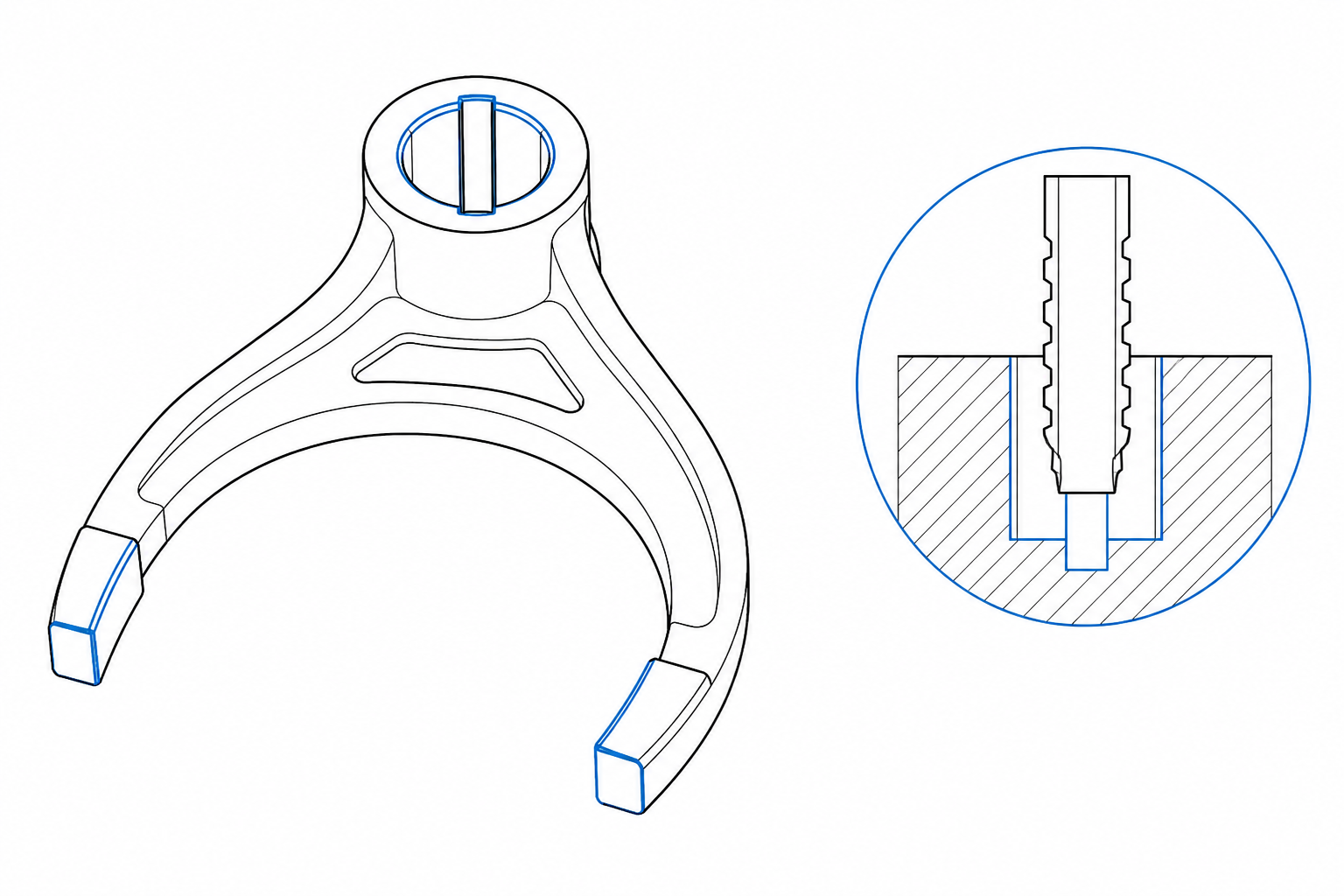
Inside every manual and dual-clutch gearbox, gear selection is mechanical work. Motion travels from the shifter through the selector mechanism to the shift rails, and at the end of that chain a shift fork converts axial travel into movement of the synchronizer sleeve. The fork’s fingers ride in an annular groove on the outside of the sleeve, so every shift is, quite literally, the fork pushing the sleeve into mesh. How cleanly that happens — and how long the synchronizer assembly lasts — depends on how accurately the fork is machined.
That accuracy is exactly why shift fork production interests broaching engineers. A shift fork is not a round part, and most of its geometry belongs to forging, milling, and grinding. But the features that locate and orient the fork — the hub bore it mounts to or slides on, and the keyed or splined connections inside that bore — are classic internal broaching territory. The hub-bore keyway, internal spline, or formed groove is where a broach earns its place on a fork line, and it is also where the tolerances that govern shift quality live.
This article walks through gear shift fork broaching feature by feature: what the part does, which features go to a broach and which do not, material behavior under a broach, volume economics, fixturing and distortion control, tolerances and inspection, and machine selection — in the same workpiece-case format as our other driveline component studies.
What a Gear Shift Fork Does in a Transmission
A shift fork is the interface between the shift mechanism and the synchronizer. In a typical layout, each fork pairs with one shift rail and one synchronizer sleeve. When the rail moves, the fork moves with it, and its two fingers — engaging the circumferential groove machined around the sleeve — carry the sleeve axially along the spline teeth of the synchronizer hub. That stroke is what engages and disengages the gear pair. The fork carries real but modest loads: synchronizer reaction torque during the shift, and continuous contact against the groove flanks.
Designs vary in how the fork is attached. In many constructions the fork is fixed to the shift rail by a pin, bolt, or clamp, with the rail sliding in housing bores. In others, the fork itself slides on a stationary guide rail or on the machined hub of the synchronizer assembly. Across all of these variants, one element is constant: a hub bore whose fit — and often whose keyed or splined connection — positions the fork in space and orients its fingers toward the sleeve groove.
That orientation is the functional crux. If the hub-bore feature that sets angular position is off, the fingers sit skewed in the sleeve groove; the sleeve tilts instead of translating squarely, synchronizer loading becomes uneven, and shift feel degrades. That is why the small internal features of a fork — the very features a broach produces — carry geometric tolerances out of proportion to their size.
Which Shift Fork Features Are Broaching Candidates — and Which Are Not
The honest starting point for any workpiece case is the division of labor: broaching does not make a shift fork — it finishes specific internal features after other operations have established the shape and datums. The features that realistically go to a broach fall into a short list.
- Hub-bore keyways. Where the fork locates on its shaft or rail through a key, the internal keyway is the textbook broaching application: a straight-sided groove in a finished bore, cut in one pass with the broach guided by the bore itself. The method, tooling options, and process controls are the same ones covered in our complete guide to keyway broaching.
- Internal splines in the hub bore. Some fork designs use a splined connection to the shaft or hub — a sliding fit that lets the fork translate along spline teeth, or a fixed fit that locks angular position. Internal splines in a through-bore follow the same broaching practice used on other transmission components, with the fork’s irregular body as the main difference.
- Formed and profiled grooves. Detent grooves for locking balls, shaped grooves that carry the shift mechanism’s locating function, and other straight-through internal forms can be broached where the geometry runs parallel to the stroke direction. If the form can be generated by a cutter translating along the bore axis in one line, it is a broaching candidate regardless of how irregular its cross-section looks.
Equally important is what is not broached. The finger faces that ride in the sleeve groove are external, open-faced geometry; they are milled, ground or fine-machined where tolerances demand, and often surface-treated for wear. The fork body outline comes from the forging or powder-metal blank, and the hub bore itself is drilled, reamed, or bored before broaching — internal broaching pilots on the finished bore, so the bore defines the feature. A process plan that respects this division is the difference between a broach that holds tolerance for the life of the tool and one that fights the part.
Shift Fork Materials and How They Behave Under a Broach
Most volume-produced shift forks start as forged steel. Forgings suit the part well: the slender body, hub, and fingers form close to net shape with grain flow running where the loads run, leaving machining only on the functional surfaces — the bore, its internal features, and the finger faces. The steels are conventional engineering grades, and fork blanks reach the broaching operation in a heat-treatment state defined by the drawing; that state is a direct input to the broach design.
The other common route is powder metallurgy. Compacted and sintered to near-net shape, powder-metal forks need very little machining — exactly their appeal at automotive volumes. For a broaching engineer, the forming route matters less than the material state: hardness, density, and microstructure set the tooth load the broach can carry, chip formation, edge preparation, and how the tool wears over its reconditioning cycle. Powder-metal parts bring added considerations around porosity at cut edges, which tool designers account for in tooth geometry.
The practical takeaway: material condition belongs in the first exchange with a broaching supplier. The same feature cut in two different material conditions calls for two different broaches — tooth spacing, rake and clearance angles, coatings, and tool-life expectations all shift with it. Specifying material and hardness up front is how you get a tool that holds the tolerance instead of merely reaching it.
The Volume Economics of Broaching a Mass-Production Part
Shift forks are quintessential automotive-volume parts: a single gearbox carries several, so the annual volume of any one fork design is a multiple of vehicle production. That is precisely the regime where broaching competes, and it deserves a clear-eyed comparison rather than a reflexive answer.
Broaching wins on consistency and cycle time. One stroke generates the complete internal form, so the geometry lives in the tool rather than in machine kinematics or an operator’s offsets; part-to-part variation tracks tool wear, which is gradual and predictable, instead of the stack-up of a multi-step routine. On a high-volume line, a dedicated internal broach cutting a fork keyway in seconds fits naturally into a cell layout, and that repeatability is what lets downstream assembly and shift-quality audits run without surprises.
Milling wins on flexibility. A machining center already on the floor can cut an internal keyway or slot with no dedicated broach to purchase, and it absorbs design changes and low-volume multi-variant programs without tooling consequences. For prototype forks, aftermarket runs, and small programs, milling is usually the right call.
The decision is therefore a volume decision, made explicitly: a broach is ground for one feature on one part family, and the tooling investment amortizes against saved machine time and gained consistency as volume rises. We lay out the comparison — tooling cost, cycle structure, tolerance behavior, and where each process stops making sense — in broaching vs. milling for internal keyways and profiles.
Fixturing an Irregular Part: Datums, Support and Distortion Control
Shift forks are awkward parts to hold. Unlike the discs, hubs, and rings that make up most internal broaching work, a fork is a slender, offset, asymmetric body — a hub at one end, two thin fingers reaching away from it, and not much else. You cannot drop it onto a through-rod the way you would a ring gear. The fixture is engineered around the part, and on high-volume fork lines it is as much a design deliverable as the broach itself.
Datum strategy comes first, and the guiding principle is datum consistency: the broached feature must relate to the same datums the part functions on. Because an internal broach guides in the bore, the hub bore is naturally the primary datum — the bore positions the tool, so the feature is located to the bore by construction. What the fixture adds is the angular and axial references: clocking the keyway correctly relative to the fingers, and depth from the reference face. The angular datum is often a machined pad, the finger envelope, or a dedicated process feature, and it must be one the rest of the process chain already respects.
Distortion control is the second discipline. The broaching cut removes material from inside the hub while reaction loads push outward into the surrounding walls, and on a fork those walls connect to thin, compliant fingers. Poor support lets the hub yield elastically during the cut and spring back after it, so the feature measures differently in the fixture than on the checking fixture. Good fixturing answers with support directly under the hub, clamping against solid material rather than the fingers, and — where the design allows — sequencing broaching before finish machining of features it would disturb. On particularly slender forks, the fixture may carry adjustable finger-end supports purely to keep the body from acting like a spring.
At volume, fixtures also carry the productivity argument: multi-part fixtures load several forks per stroke and spread stroke time across parts, with the caveat that total cutting load must be checked against machine capacity — the fixture bar is a tonnage decision as much as a convenience. The same fixture concept is what later connects the broaching station to automated loading.
Tolerances and Inspection: Position, Symmetry and Slot Width
The inspection scope on a broached shift fork feature clusters into three groups. Size — keyway width or spline tooth thickness — governs the fit to the mating key or shaft and is controlled on the broach by design and reconditioning. Form and finish in the cut feature affect function quietly but cumulatively. And then there are the geometric relationships, which on a fork carry the real weight: the angular position of the keyway or spline relative to the fingers, the symmetry of the feature about the bore’s reference, and the relationship of the feature to the part’s end faces.
Angular position deserves special emphasis because it is the chain link between the broaching operation and the customer’s shift quality. The keyed or splined feature clocks the fork on its shaft; clocking sets where the fingers point; where the fingers point sets how squarely the sleeve moves. A keyway that meets its width tolerance but sits off its angular position produces a dimensionally “good” part that functions badly. Drawings encode this as true position or angularity to the finger datum, and broaching inherits it through the fixture’s angular reference — which is why fixture design and tolerance review belong in one conversation.
On the shop floor, the scheme mirrors every other high-volume internal feature. Functional gaging — a go/no-go plug for size, and a receiving gage that simulates the mating shaft with the angular reference built in — checks the feature the way the transmission will use it, at production speed. Coordinate measuring machines sample the same characteristics at lower frequency for full geometry, capability studies, and gage validation, and statistical process control tracks the broached feature like every other characteristic in the control plan.
One discipline easy to underweight: burrs. A burr in the hub bore can shed into the gearbox’s lubricant and find the synchronizer; a burr at the finger roots or faces interferes with the sleeve groove. Deburring and burr verification belong inside the broaching operation’s scope, not at the end of the line, and edge condition belongs in the process documentation with the same seriousness as width and position.
Machine Selection: Vertical Internal Broaching and Automation
For the hub-bore features that dominate shift fork broaching, the default answer is a vertical internal broaching machine. The logic is straightforward: the features are short, the part is small, the broach guides in the bore, and a vertical stroking axis with the part fixtured on the table keeps the setup compact and chip flow clean. Keyways run with the standard setup — broach guided in a horn or bushing aligned to the bore — while splines and formed grooves use the corresponding dedicated internal broaches in the same machine concept.
Sizing the machine is a calculation, not a guess: force follows from the feature geometry, the tooth rise built into the broach, the material and its condition, and the number of parts fixtured per stroke — and the machine should carry margin above the calculated load so the reconditioning cycle and any fixture-bar growth fit inside its capacity. Stroke length follows the feature plus approach and exit clearance, and the tool interface follows the fixture design.
The other half of machine selection at fork volumes is automation, and it belongs in the specification from the start rather than retrofitted. A dedicated station earns its keep when loading, stroking, and unloading run as one rhythm: parts arrive oriented from upstream machining, are loaded into the multi-part fixture by a pick-and-place unit or shuttle, are broached in the loaded set, and leave for washing and gaging without an operator in the loop. In-machine probing and integrated gaging extend this, closing the loop between tool wear and compensation — and the machine’s control and interface provisions differ when the station is automated, which is why the automation intent belongs in the original specification. The configurations and options are covered in the broaching machine overview.
Related Broaching Case Studies in Driveline Components
Shift forks sit in a family of transmission and driveline parts where the same broaching logic applies: an internal formed feature, a high-volume program, and relationship tolerances that decide function. Three case studies on this site cover the pattern from different angles. Transmission gear internal spline broaching works through the classic internal spline application at gear-production volumes, including tolerance strategy and inspection. Steering wheel hub internal spline broaching covers the same discipline on a forged blank, from spline data through tool design to bore preparation. And connecting rod broaching shows the other side of the pattern — a part where broaching holds a narrow scope inside a process chain dominated by boring and honing, exactly the division-of-labor reasoning a fork line also needs.
The common thread is the working rule behind every one of these applications: when a formed internal feature repeats at production volume and its geometric relationships decide how the assembly behaves, the process that generates the whole form in one guided stroke — geometry locked in the tool — is the one that holds tolerance over the life of the program.
Frequently Asked Questions
Can you broach a gear shift fork?
Yes — for specific features, not the part as a whole. What a broach produces on a shift fork are the internal features of the hub bore: keyways that key the fork to its shaft or rail, internal splines where the design uses a splined connection, and formed grooves such as detent or locating grooves that run straight through the bore. The finger faces and body outline are not broached — they belong to milling, grinding, and the forging or powder-metal blank — and the bore itself is machined first, since the broach pilots in the finished bore.
What type of broaching machine is used for shift forks?
A vertical internal broaching machine is the typical answer, because fork features are short internal forms cut in a small bore with the tool guided by the bore or a bushing. Multi-part fixtures spread the stroke across several forks per cycle at volume, and selection comes down to stroke length, calculated force capacity with margin, tool interface, and — on high-volume lines — the automation interface, specified with the machine rather than added afterward.
What are shift forks made of, and does it matter for broaching?
Volume-production forks are predominantly forged steel, with powder-metallurgy forks common where near-net compaction pays off at high quantities. It matters directly: material and heat-treatment condition set tooth loads, chip behavior, edge geometry, coatings, and tool life between regrinds, so the same feature in two material states calls for two different broaches — one of the first data points a tool designer asks for, alongside the drawing and annual volume.
What production volume justifies broaching fork features?
There is no universal threshold, because the break-even is a cost comparison, not a part count: the dedicated broach and fixture amortize against machine time saved per part and consistency gained, so the answer depends on the feature, the cycle it replaces, and how many variants share the tooling. As a working pattern, prototypes and short runs are milled; sustained production volumes are where broaching’s one-stroke, tool-defined consistency pays. The practical route is to price both against the actual drawing and forecast volume.
If you are machining shift forks — or quoting a fork program — and need an internal broaching operation engineered around the features on your drawings, that is precisely what we do. Send the part prints, material condition, and annual volumes, and we will return a machine and tooling configuration with force capacity, stroke, and fixturing worked out for the part. Start with the machine overview linked above, or go straight to our engineering team with your workpiece details.