

Engineering concept only. It is not a size chart, released dimensioned drawing, tolerance recommendation or proof that every keyway is suitable for a particular tool or machine.
A search for keyway dimensions often leads to a chart. A chart can be useful for preliminary reference, but it is not the starting point for making, inspecting or quoting a real keyway. The controlled drawing, its revision and its governing document decide what the part requires.
This guide helps engineers, buyers and production teams read a keyway callout before a tooling or process review. It distinguishes a shaft keyseat from an internal bore keyway, identifies the drawing fields that affect the route, and explains why a standard designation must be read with its edition, unit system and any customer-specific override. It does not reproduce ANSI, ISO, DIN, BS, JIS or proprietary size tables.
For the process itself, see Räumen von Keilnuten: Der vollständige Leitfaden. For a blind-end condition, see Blind Keyway Broaching.
The Short Answer
Before selecting a keyway broach, bushing, fixture or machine, identify the exact feature and the controlled drawing requirement. Confirm whether the feature is a keyseat on an external shaft or a keyway inside a bore; then record its location, datum references, width, depth, length, end condition, root/corner condition, material stage, accessible entry/exit and acceptance method.
A standard reference can help explain the notation, but it does not override the released drawing. Do not infer a dimension, fit, tolerance class or inspection method from a generic online table when the controlled document says otherwise.
1. Start With the Controlled Definition
The same informal word—“keyway”—can refer to different mating features. A complete review needs more than a nominal width and depth. Begin by collecting:
- the controlled drawing or model and revision;
- part name and exact feature location;
- unit system and any named governing standard/edition;
- customer notes, general tolerances and special acceptance requirements;
- material, heat-treatment and upstream machining stage;
- related mating-key, shaft, hub or bore information where specified;
- the production quantity pattern and required inspection record.
If the drawing refers to another document, obtain that document through the design authority or approved standard source. A secondary chart may be a useful sanity check, but it is not authority to alter the part definition.
2. Shaft Keyseat and Bore Keyway Are Different Feature Problems

Non-dimensional feature map. It distinguishes location and access questions; it does not define any standard geometry or tolerance.
Shaft keyseat
A shaft keyseat is an external feature formed along a shaft or similar outside diameter. The part may be supported and located differently from a bore feature, and the cutting access can be open from above or from the side. The drawing must state the actual datum relationship, axial location, length, end condition and surface-protection requirements.
Do not treat a shaft keyseat as proof that an internal keyway process, bushing or pull route applies. External support, force reaction, part deflection and inspection access can be entirely different.
Internal bore keyway
An internal keyway is cut inside a bore, hub or similar enclosed feature. The available entry, tool exit, shoulder condition, bore preparation and keyway end condition control whether a progressive broach, single-point route, keyseater or another method can be reviewed.
The drawing should make clear which bore or face establishes the feature location, whether the keyway is through or blind, and whether there is a relief, exit space or protected region. Räumen von Keilnuten: Der vollständige Leitfaden covers the process-side considerations; this article keeps the focus on reading the controlled requirement.
3. Fields to Identify Before Tooling Review
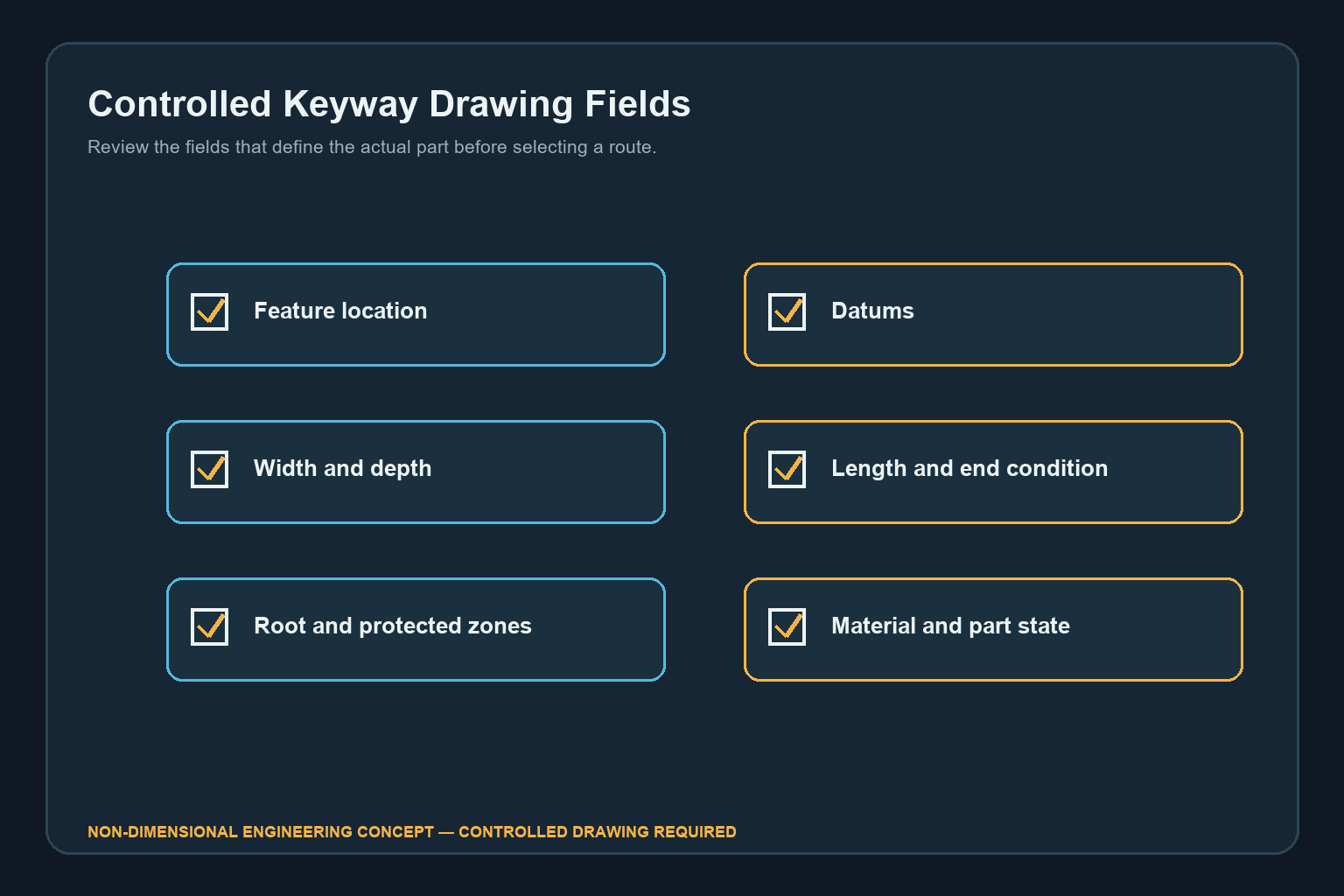
Conceptual drawing-review map. The actual controlled drawing determines the values, datums and acceptance criteria.
Location and datums
Identify the bore, outside diameter, face, axis or angular reference that controls where the keyway belongs. A keyway can have an acceptable nominal width while still be unacceptable if its location is referenced from the wrong face, bore or angle.
Ask how the same reference is established during machining and inspection. If production locates on one surface while final acceptance uses another, the relationship needs a deliberate fixture and measurement plan.
Width, depth and feature extent
Record the dimensions exactly as controlled, including any local notation that changes what “depth” is measured from. Check whether the feature is full length, limited length, interrupted, through, blind, open-ended or relieved. Do not replace an explicit drawing definition with a presumed standard relationship.
Root, corners and transitions
Corner relief, root condition, runout, chamfer and adjacent shoulder details can change the tool-entry, chip-exit and inspection discussion. If the drawing is silent, do not add a generic radius or relief as though it were an approved requirement. Escalate the ambiguity to the drawing owner before ordering tooling.
Material and production stage
The material condition can affect both the candidate process and the result that must be checked. State whether the feature is reviewed before or after heat treatment, coating, finishing or another operation. Hard vs Soft Broaching gives context for process timing; it does not set a material route for an unreviewed part.
4. Read a Standard Designation as a Controlled Reference
A keyway callout may refer to an external standard, a company standard or a customer document. The useful questions are:
- Which exact document and edition is named?
- Which unit system and feature family does it cover?
- Does the drawing give an explicit value, tolerance or exception?
- Do general notes, mating-part requirements or customer specifications add constraints?
- Who is authorized to resolve a conflict between documents?
The designation does not remove the need to inspect the released drawing. It provides a reference framework that must be interpreted in the context of the specified part. If the document is unavailable or its application is unclear, stop the tooling decision and request clarification rather than guessing a fit or tolerance.
Why generic tables create risk
Public size charts often omit revision, feature orientation, unit-system convention, mating context, general tolerances, manufacturer notes and local drawing overrides. They may also combine shaft and bore guidance in a way that looks interchangeable. Use them only as discovery material, not as a substitute for current controlled source material.
5. Convert the Drawing Into a Process-Review Package

Conceptual checklist. It identifies inputs for an engineering review; it is not a tool specification, dimensional chart or production approval.
When requesting a broaching review, provide the full definition rather than only a nominal key size:
- drawing/model revision and all governing notes;
- exact shaft or bore feature identity;
- material, hardness or heat-treatment stage where relevant;
- bore or shaft preparation and accessible entry/exit;
- feature length, end condition and protected zones;
- functional datums and mating-component information;
- forecast, lot pattern and expected revision frequency;
- required inspection method, gage information and first-article expectations;
- available machine, fixture, loading and coolant constraints.
These inputs allow the candidate broach, holder, machine, fixture and chip route to be considered as one system. They do not guarantee that a given configuration is feasible. For the tooling-design conversation, see Entwurf von Räumwerkzeugen.
6. Keep Inspection Linked to the Drawing
Inspection should answer the requirement actually released. Define the part state, datum setup, characteristic, method category and authority that interprets the result. A width check, depth check, visual review and functional mating check can each answer different questions.
Do not call an informal measurement a final acceptance result merely because it is convenient. If a supplier and customer use different methods, determine whether they are correlated before comparing results. The required inspection plan should be part of the quotation and first-article discussion, not an afterthought after tooling is committed.
Separate production evidence from feature acceptance
Tool condition, fixture cleanliness, cutting-fluid control and machine signals can support process stability. They do not automatically prove that a finished keyway meets the drawing. Conversely, an inspection discrepancy may require investigation without proving which production variable caused it. Keep the evidence streams connected but distinct.
7. Route Through and Blind Conditions Correctly
A through internal keyway can offer a different access and chip path from a blind feature. A progressive route may be reviewed for a suitable through condition, while a blind end may need controlled stopping, relief, chip space or another process route. Do not treat the word “keyway” as enough information to choose between them.
When the drawing shows a blind condition, use Blind Keyway Broaching for the access and relief questions. When the decision is between broaching and keyseating, treat it as a separate method-selection review rather than extending this drawing-interpretation guide into a cost or process comparison.
Häufig gestellte Fragen
Can I use a standard keyway chart instead of the drawing?
No. A chart can be a preliminary reference, but the released drawing, named governing document and authorized design/quality interpretation control the actual part.
Are shaft keyseats and bore keyways interchangeable?
No. They may relate to the same key connection, but feature access, location, workholding, tool path and inspection can differ substantially.
Does a standard designation select the machining method?
No. It identifies a reference framework. The actual feature, material stage, access, quantity, tooling, machine, fixture and inspection plan determine what process can be considered.
What should I send before requesting a broaching quote?
Send the controlled drawing/model, revision, feature location, material/stage, entry/exit condition, expected quantity, datum/inspection requirements and any available machine or loading constraints.
Why does a nominal keyway size not complete the review?
The nominal size does not state every necessary condition. The review also needs the feature location, the reference used for depth and position, end condition, material stage, accessible entry/exit, inspection requirement and any customer-specific override.
Can a drawing use a standard and an explicit exception together?
Yes. A drawing can reference a standard framework and still state a local dimension, tolerance, finish, datum or inspection requirement. The authorized drawing interpretation determines how those documents apply to the released part.
8. Use a Drawing-Review Handoff Before Production
Before a quotation, tool order or first trial, convert the drawing review into a short controlled handoff. Identify the document revision, feature identity, unresolved questions, engineering owner, proposed process-review date and the inspection authority. If a referenced standard or note is unavailable, make that a visible open item instead of filling the gap with a generic online chart.
This handoff makes later changes easier to control. When the feature, material state, datum scheme or acceptance method changes, the team can decide whether the tooling, fixture and inspection plan need re-review. It also creates a clear boundary between design authority and manufacturing input: the process team can identify what it needs to know without silently redefining the part.
Suggested review sequence
First, check that the supplied drawing and model identify the same revision and feature. Next, separate the information that comes directly from the drawing from information that must be confirmed by the customer, design owner or inspection authority. Then ask the process reviewer to assess only the documented feature condition—shaft or bore, entry/exit, material stage and required production pattern.
After that, establish the candidate machine, tooling, fixture and inspection assumptions for a controlled trial. Record any remaining uncertainty as an action item. The final step is not “choose a chart”; it is to confirm that the actual process and inspection plan both reproduce the released part definition.
Avoid changing several variables at once
When a first sample is not accepted, resist the urge to modify the tool, fixture, material condition and measurement setup together. Confirm the drawing revision and datum setup first, then contain the result and investigate one controlled cause path at a time. This discipline is useful even when the feature is simple because it prevents a temporary adjustment from being mistaken for a validated production route.
Start With the Drawing, Then Review the Route
Keyway dimensions become useful manufacturing inputs only after the team knows what the controlled drawing means for the actual shaft or bore feature. Send the drawing, material/stage, feature access and inspection requirement through the Kontaktseite for a BroachingMach review of the broaching portion of the route.


