
Turbine-disc slot broaching is the controlled production of circumferential blade-root slots around an aero-engine or industrial gas-turbine disc. The target feature may be a multi-lobed fir-tree slot or a simpler dovetail slot. Both are external profiled slots, but they are not interchangeable geometries, and neither term describes the separate requirement to index every slot around the disc.
This article is a Tier C engineering guide, not a customer case study. It explains a candidate process based on public manufacturing evidence and relevant BroachingMach product architecture. The final broach geometry, machine, fixture, force, stroke, accuracy, cycle time and tool-life expectations require a controlled drawing review, calculation and sample broaching. For context, see the existing turbine-disc processing Solution Page; its project-level claims are not reused here without supporting records.
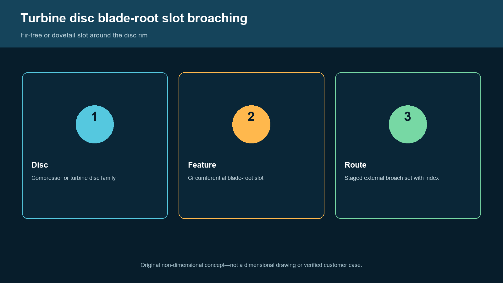
Engineering concept illustration, not a dimensional drawing, delivered machine or verified customer part. The highlighted slot and staged tooling communicate the process route only; final geometry requires drawing review and sample validation.
Define the Exact Disc and Slot Before Selecting a Broach
A useful proposal starts with the semi-finished workpiece, not with a machine model. The disc may be a compressor disc, turbine disc or industrial power-generation disc, and those families can differ in envelope, material, heat treatment, slot direction and production route. “Turbine part” is too broad because a blade root, a disc slot and a blisk require different manufacturing decisions.
The controlled feature is the female slot in the disc rim that receives a blade root. Four inputs must be frozen:
| Input | What must be controlled | What remains open at Tier C |
|---|---|---|
| Workpiece | Exact disc family, revision and manufacturing stage | Diameter, thickness, mass and variants |
| Slot form | Fir-tree or dovetail; straight or angled relative to the disc axis | Finished profile, radii and contact faces |
| Circumferential pattern | Slot count, angular pitch and clocking datum | Index tolerance and verification method |
| Material condition | Alloy specification and heat-treatment state | Hardness range, certificate and stock distribution |
A fir-tree slot uses multiple lobes and necks to distribute load across mating faces. A dovetail uses a simpler converging form. The number of lobes, flank angles, root radii and contact zones come from the controlled drawing; they cannot be inferred from the component name. Likewise, a visually acceptable slot can still be unacceptable if its angular position relative to the disc datum or adjacent slots is wrong.
Freeze the Manufacturing Stage and Pre-Slot Condition
Broaching is only one operation in a high-value disc route. Before slotting, the forging or blank normally passes through turning and other preparatory machining. Depending on the approved route, a pilot or pre-slot may be milled to remove bulk stock and reduce the load on the profiled broaches. Public aerospace tooling literature also distinguishes pre-milling from subsequent slot broaching.
The proposal therefore needs a map of the incoming slot:
- material and heat-treatment condition at broaching;
- pre-slot width, depth, end condition and alignment;
- stock remaining on each flank, root and pressure face;
- burrs, scale, interrupted surfaces or local hard zones;
- surfaces already finished and requiring protection;
- operations planned after broaching, such as deburring, edge rounding, peening or additional inspection.
Edge rounding is not the same as slot broaching. Broaching can leave burrs or sharp edges, and a later controlled finishing operation may be required. That operation needs its own acceptance criteria because uncontrolled rounding can change critical profile zones. Similarly, milling, grinding, EDM/WEDM and electrochemical routes are genuine alternatives or complementary stages for some disc programs. Broaching should be selected because the approved production, quality and economic case supports it—not because every fir-tree slot must use the same process.
Separate Fir-Tree Profile, Dovetail Profile and Slot Indexing
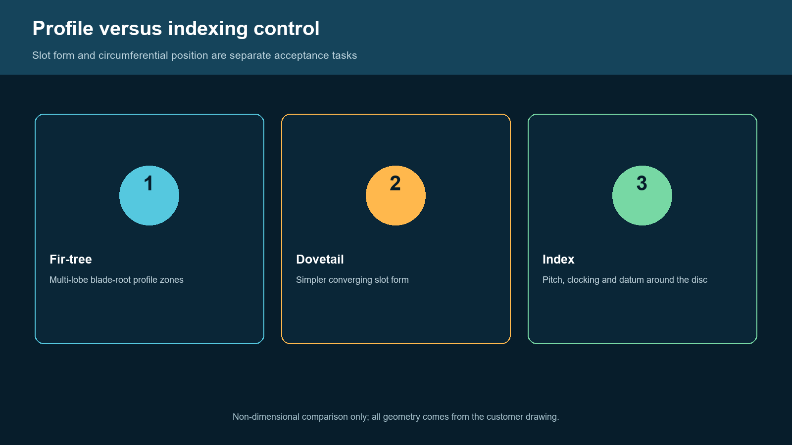
Non-dimensional engineering diagram. The slot profile and the circumferential indexing pattern are separate controls; all dimensions and contact zones must come from the customer drawing.
Profile control asks whether the individual slot matches its required form. Depending on the drawing, inspection may address flanks, pressure faces, necks, root radii, slot depth, symmetry, edge condition and surface integrity. The fir-tree profile can have several functional zones, while the dovetail form has a different contact and relief strategy. A tool designed for one drawing is not a universal “fir-tree broach.”
Indexing control asks where that slot sits around the disc. The fixture must reference an approved bore, face, pilot or other datum, rotate the workpiece by the controlled pitch, lock it against the cutting load and verify the next position. Errors can arise from datum contamination, seating tilt, fixture compliance, backlash, thermal change or an incorrect part program. Measuring one slot profile does not prove the full circumferential pattern.
This separation affects the quality plan:
- qualify the datum and fixture seating;
- verify the first slot’s clocking relationship;
- inspect the individual profile;
- verify pitch or index relationships across the specified pattern;
- repeat checks at the drawing-defined frequency and after any abnormal event.
Plan a Rough, Semi-Finish and Finish Broach Set
A turbine-disc slot is commonly produced with a sequence of tools or tool sections rather than a single cutter that instantly creates the final form. The exact segmentation is application-specific, but an engineering plan usually separates functions:
- Roughing tools remove the planned bulk stock while controlling chip load and avoiding an unstable full-profile engagement.
- Semi-finishing tools develop the major flanks and transition zones, balance remaining stock and prepare a consistent condition for finishing.
- Finishing tools generate the drawing-controlled final zones with a small, known allowance.
- Calibration or sizing elements, if the approved design uses them, stabilize selected dimensions; they do not correct a bad datum or grossly uneven incoming stock.
The cutting sequence must be designed as one system. Tooth rise, pitch, rake, clearance, chip space, tool material, coating, guide surfaces and overall length interact with the workpiece alloy and remaining stock. For that reason, a set of special broaches should be evaluated against the controlled slot drawing and process route. The broach tooling design process should also include interfaces, handling, inspection, resharpening and replacement criteria—not only the cutting profile.
Chip formation is especially important in difficult alloys and multi-flank engagement. The design needs enough chip space for each stage, a verified exit path and a coolant strategy compatible with the workpiece, tool and downstream requirements. Packed chips, material pickup, unexpected load growth or an incomplete tool exit are stop signals, not conditions to overcome by increasing force without review.
Select the Machine and Rotary Fixture as One System
Public machine literature shows both horizontal and vertical turbine-disc broaching architectures. The correct orientation is not chosen from the slot name alone. The selection must close the following envelope:
| Module | Candidate requirement | Validation question |
|---|---|---|
| Machine | External/surface broaching architecture with adequate force, stroke, daylight and rigidity | Can the complete broach set and disc envelope move safely through the full sequence? |
| Tool interface | Guided holder, rail or cassette appropriate to the tool set | Is alignment maintained during loading, cutting and tool change? |
| Rotary fixture | Qualified datum, radial/axial support, index drive and positive locking | Does the cutting load close through stable reaction zones without disc movement? |
| Controls | Recipe control, index verification, load monitoring and interlocks | Can the system prevent wrong-part, wrong-tool and wrong-position operation? |
| Coolant/chips | Directed delivery, filtration, collection and safe cleaning | Are chips cleared without damaging the profile or contaminating the datum? |
BroachingMach has relevant horizontal and vertical architecture references, including the horizontal tenon-and-groove machine, the vertical mortise-and-groove machine and the broader surface broaching machine family. These links identify candidate machine classes only. They do not prove that a listed configuration fits a specific disc.
The horizontal broaching machine and vertical broaching machine families provide additional orientation context. A final choice requires the disc envelope, tool length, workpiece/tool motion, loading plan, foundation, automation, service access and inspection integration.

Candidate engineering route, not a released machine specification. Tool segmentation, workpiece motion, fixture design and inspection frequency remain subject to drawing review and sample trials.
Fixture load path and protected zones
The fixture must do more than rotate the disc. It must locate the workpiece repeatably, support it without distortion, resist cutting force and overturning moment, and keep finished surfaces out of damaging clamp contact. The engineering review should mark:
- the primary axial face and radial/central datum;
- acceptable support and clamp regions;
- no-clamp zones such as seal features, finished bores, threads or fragile edges;
- the cutting-force reaction path through disc, fixture and machine;
- chip-exit and cleaning access;
- index drive, lock and independent verification features.
If the support arrangement changes between disc variants, the changeover needs a controlled fixture configuration and a verification part or routine. “One rotary fixture for all turbine discs” is not an acceptable assumption.

Original non-dimensional engineering concept. It is not a released machine specification, verified customer case or dimensional drawing.
The CNC hydraulic external tenon broaching machine family may be relevant to a candidate external-profile route, but its applicability to a new disc must be calculated and confirmed.
Run the Process as a Closed Quality Loop
A controlled slot-broaching route should connect part identity, cutting, inspection and tool condition:
- Confirm the disc family, drawing revision, route card and slot program.
- Verify material/heat-treatment records and inspect the incoming pre-slot and datum.
- Confirm the approved rough, semi-finish and finish tool sequence.
- Inspect tool edges, guides, holders, fixture contacts and index lock.
- Load the disc on clean datums, support protected zones and confirm chip clearance.
- Establish the first index and independently verify clocking before cutting.
- Apply the approved coolant and run the controlled broaching stroke.
- Monitor load trend, sound, chip shape, movement and coolant delivery.
- Clean the slot and datum without damaging finished edges.
- Inspect the slot profile and the specified index relationship.
- Release the next position only when tool, part and process checks are acceptable.
- Record part, slot, tool-set, fixture, recipe, inspection and abnormal-event data.
An in-cycle load trace is valuable process evidence, but it is not dimensional acceptance. Likewise, a profile reading taken while the part is distorted by clamping may not represent the released component. Final acceptance must use the customer-approved free-state setup and reference method.
Build Inspection Around Function and Correlation
The inspection plan should start from the drawing’s functional zones. CMM, profile measurement, optical comparison, dedicated gauges and roll-pin or other comparative methods may each have a role. The chosen method must be capable of resolving the required profile and datum relationship, and BroachingMach measurements must correlate with the customer’s reference method.
| Acceptance item | Reference evidence |
|---|---|
| Individual slot profile | Raw profile/CAD comparison or approved gauge results |
| Circumferential index | Readings related to the controlled disc datum and slot pattern |
| Surface and edge condition | Specified roughness/surface-integrity method plus visual records |
| Part protection | Inspection of clamp, support and handling zones |
| Process stability | Slot-by-slot load/chip observations linked to measurement data |
| Tool condition | Before/after inspection of cutting edges, guides and pickup |
A sample plan should include representative normal parts and the agreed worst-case incoming condition. First-article approval, a short repeatability run, factory acceptance, site acceptance and stable production are separate gates. Passing one sample does not establish a universal capability.
Set Tool-Life and Regrind Criteria From Trends
No responsible proposal should promise a fixed number of slots between regrinds without project data. A baseline should instead record edge condition, tool geometry, coating status, load signature, chip appearance and accepted slot measurements. Change criteria can then combine:
- progressive load increase or instability;
- profile or size drift;
- surface deterioration or burr change;
- edge chipping, pickup or abnormal wear;
- altered chip formation or evacuation;
- loss of guide or interface condition.
When a stop limit is reached, the affected tool and parts since the last accepted check should be quarantined for review. Resharpening must preserve the released form and remaining life allowance. Recoating, replacement and any process compensation require controlled approval rather than an operator’s ad hoc offset.
Information Needed for a Turbine-Disc Broaching Proposal
To evaluate a candidate solution, provide:
- controlled disc drawing and CAD model;
- exact disc family, variants, annual/shift volume and changeover needs;
- material specification, heat treatment and hardness range;
- incoming pre-slot geometry and stock map;
- fir-tree or dovetail profile, functional faces, radii and edge requirements;
- disc datum, slot count, angular pitch, clocking and inspection method;
- protected surfaces and handling restrictions;
- current manufacturing route and approved alternative processes;
- coolant, cleaning and surface-integrity requirements;
- representative normal and worst-case samples;
- customer gauge/CAD data and acceptance/reporting requirements;
- available machine, floor-space, automation and service constraints.
These inputs allow BroachingMach to evaluate the candidate broach set, machine architecture, rotary fixture, chip-control method and inspection plan. Final tool geometry, machine capacity, cycle time, accuracy and tool-life expectations are confirmed only after calculation and sample broaching.
Frequently Asked Questions
Are fir-tree and dovetail slots the same?
No. Both can retain blade roots, but their profile geometry and functional contact zones differ. The controlled drawing determines the tool form, stock sequence and inspection plan.
Does every turbine-disc slot require broaching?
No. Milling, grinding, EDM/WEDM, electrochemical and hybrid routes exist. The manufacturing stage, material, geometry, volume, surface-integrity rules, tooling economics and approved aerospace process determine the route.
Why separate rough, semi-finish and finish broaches?
Segmentation allows bulk stock removal, profile development and final sizing to be controlled independently. The exact number of tools or sections is calculated from the drawing, material, allowance and machine envelope.
Can profile inspection prove the disc is correctly indexed?
No. Profile conformance describes one slot; indexing describes its angular relationship to the disc datum and other slots. Both require explicit verification.
Should the machine be horizontal or vertical?
Either may be technically possible. Disc size and mass, broach length, force, stroke, workpiece/tool motion, loading, chip control, foundation and automation determine the preferred architecture.
Can one broach set process every disc variant?
Only if a controlled engineering review proves the profiles, allowances, materials, interfaces and acceptance requirements are compatible. Similar-looking slots are not sufficient evidence.
From Concept to a Sample-Validated Solution
A turbine-disc slot project succeeds when five decisions agree: the exact fir-tree or dovetail profile, the circumferential index, the staged broach set, the machine/rotary-fixture load path and the inspection method. None can be replaced by a generic accuracy claim.
Send the controlled drawing, CAD, material condition, pre-slot stock, disc/slot pattern, volume and gauge strategy through the BroachingMach contact page. BroachingMach can then review a candidate route and define the calculations and sample-broaching evidence needed before a production commitment.


