
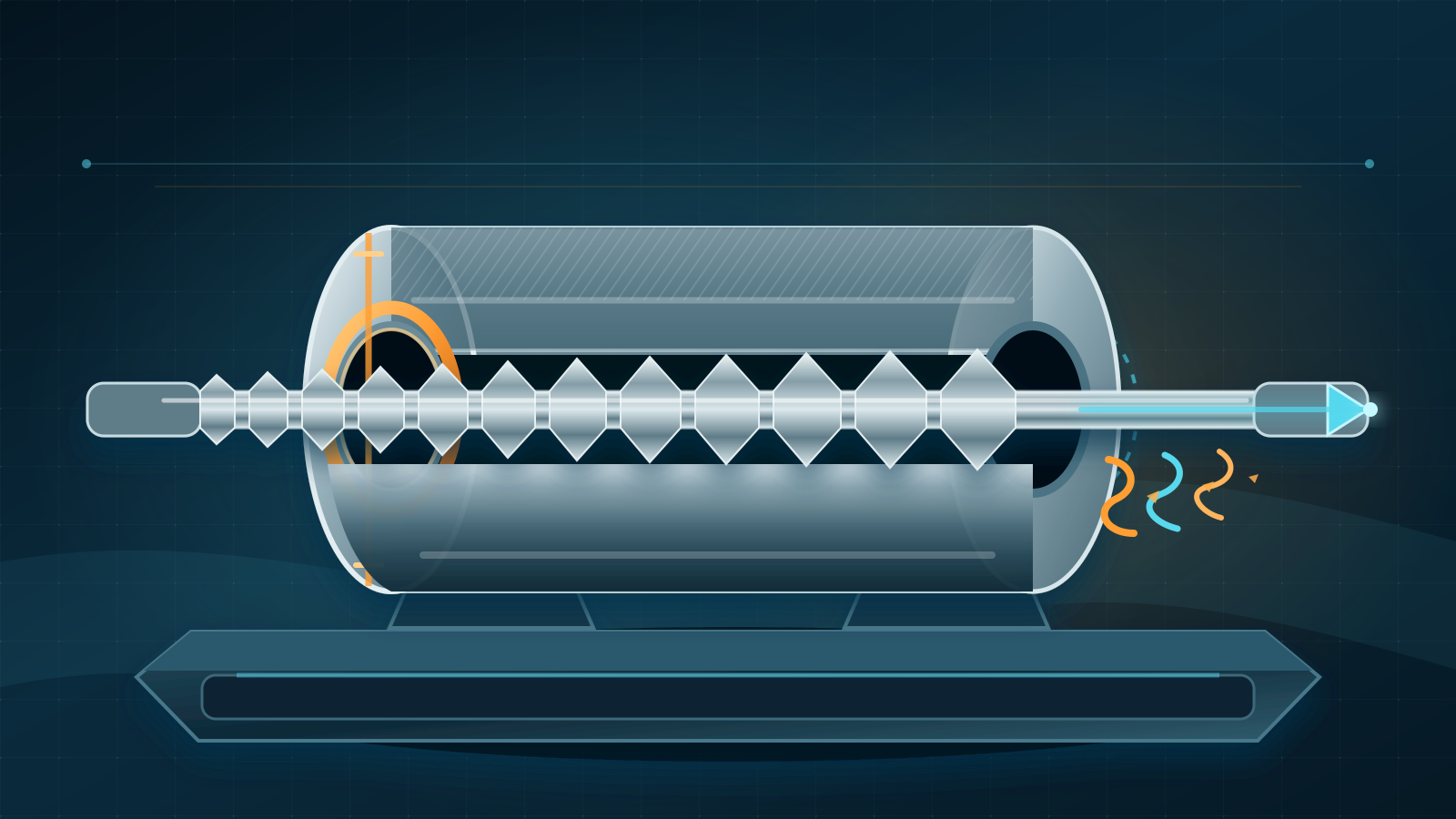
Conceptual engineering illustration comparing a prepared starting bore, entry lead, supported datum and tool-exit path. It is not a dimensional drawing, a customer project or a photograph of BroachingMach equipment.
Internal broaching part preparation begins by choosing the broaching method—not by copying a pre-drill diameter or chamfer from a chart. Progressive linear pull and push broaches, rotary broaches and CNC single-point tools remove material in different ways. Each therefore needs a different combination of starting bore, entry geometry, stock, support, chip space and tool-exit clearance.
For a new application, control the part drawing, identify the tool architecture, define the through or blind condition, and then let the tool and process design establish the preparation dimensions. Universal values are unsafe because the finished form, tool pilot, tooth progression, material condition, cut length and machine arrangement all interact.
Start with the Method Map
The term “internal broaching” covers several processes that should not share one setup instruction.
| Method | How material is removed | Preparation priority |
|---|---|---|
| Progressive linear pull | A long broach is pulled through; successive teeth increase toward the finished form | Starting-hole access, pilot guidance, pull-head clearance, supported datum and complete tool/chip exit |
| Progressive linear push | A usually shorter broach is pushed in compression, often with a guide or bushing | Square support, bore/bushing fit, column guidance, short-tool stability and exit clearance |
| Rotary broaching | A form tool is presented at a small angular offset and generates the profile by a wobble action | Tool-system pilot, functional lead-in, feature depth, chip volume and bottom clearance |
| CNC single-point broaching | One cutting edge makes repeated programmed strokes with an increment between cuts | Reference bore, relief, stroke endpoints, lateral cut clearance and safe return motion |
An index or full-form punch system may again have different rules. Treat its supplier documentation as its own process package rather than assuming it behaves like a single-point insert.
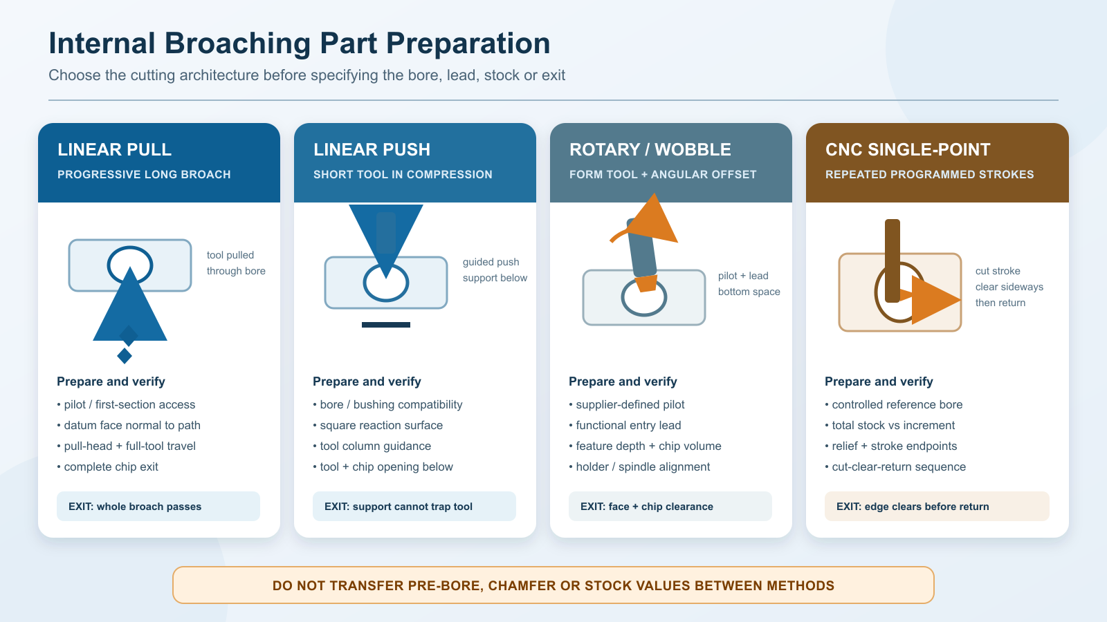
Non-dimensional method map. The labels show which preparation questions change with the cutting architecture; they do not specify production dimensions.
그리고 internal broaching machine guide explains the broader machine process. For the load-direction distinction, see push broaching vs pull broaching.
Freeze the Drawing Before Sizing the Pre-Bore
“Make the pilot hole first” is incomplete. The released drawing or controlled CAD definition should identify:
- the finished internal profile and governing standard;
- major, minor and form dimensions;
- feature length and whether it is through, blind or interrupted;
- datum references, position, runout and angular phasing;
- allowed entry and exit chamfers, corner radii and reliefs;
- material specification, hardness range and heat-treatment stage;
- coating, plating, honing, grinding or other operations after broaching;
- the inspection method and acceptance gauge.
These inputs determine what may be removed before broaching and what the broach must generate. They also prevent a common mistake: preparing a convenient hole that leaves the wrong stock distribution at corners, spline flanks or keyway depth.
If the drawing does not permit an exit relief, do not add one at the machine. If a datum changes later, the process plan must preserve its correlation to final inspection.
What the Pre-Bore Must Accomplish
A pre-bore is simultaneously an access feature, a source of stock and often a guiding reference. Its production definition should therefore include more than diameter:
- size and tolerance tied to the broach/tool design;
- roundness, straightness and taper over the cut length;
- position and runout relative to the drawing datums;
- surface condition, burr state and cleanliness;
- depth, breakthrough and bottom geometry;
- allowance for any later finishing operation.
For a progressive linear broach, the starting opening must accept the applicable pilot or first tool section and leave the stock that the designed tooth progression will remove. A pull broach also needs room for the pull end and subsequent tool sections to traverse the setup. A push broach may rely on a guide, bushing or part bore, but the compressed tool and workpiece still need stable support.
For rotary broaching, the supplier may relate the pilot to the form geometry, tool face and material. That relationship cannot be transferred to a long progressive broach. For CNC single-point work, the existing bore is commonly the reference from which programmed radial or lateral increments form the slot or spline space. Its size and location therefore affect both remaining stock and the programmed tool path.
Do not “add safety” by leaving extra stock without approval. More stock can change cutting force, chip volume, tooth loading, deflection and heat. The correct stock is the stock for which the tool, machine, fixture and validation plan were designed.
Design the Entry Chamfer as a Functional Lead
The entry chamfer or lead-in helps the tool meet the workpiece without an abrupt corner, but it performs different jobs in different methods.
In progressive linear broaching, entry geometry may protect the first cutting edges, help the pilot or guide enter, and reduce edge breakout. It must remain compatible with the finished feature and datum face. A chamfer that is too large can shorten the usable feature, alter gauge engagement or remove support near the entry.
In rotary broaching, the lead geometry is part of the vendor’s form-generation setup and can influence initial engagement. In single-point broaching, the entry edge interacts with approach distance, tool acceleration and the first cutting stroke. None of these facts establishes one universal chamfer angle or width.
Record the chamfer as a controlled feature: reference diameter, angle or profile, axial extent, allowable edge break and inspection method. “Deburr” alone is not enough when the edge is part of the cutting transition.
Separate Total Stock from Feed or Tooth Rise
Stock allowance answers, “How much material remains for broaching?” It is not the same parameter in every process.
- On a progressive linear broach, material removal is distributed by the engineered rise and spacing of successive teeth. The operator does not create a separate feed per tooth during the stroke.
- On a rotary broach, spindle motion, axial feed, tool geometry, pilot and form depth interact. A supplier’s rotary preparation chart describes that tooling system, not linear broaching.
- On a CNC single-point cycle, one edge makes repeated strokes. The programmed increment between strokes is only one part of the total stock plan.
Specify stock by comparing the controlled prepared geometry with the finished form. Review maximum-material and minimum-material conditions, corner stock, any eccentricity and upstream-process capability. Then confirm that the broach design, machine force and chip space cover the resulting distribution—not only a nominal area calculation. The broaching-machine tonnage guide provides a planning framework, but the tool supplier must validate the actual engagement.
Control the Datum, Support Face and Load Path
Part preparation includes the surfaces that locate and support the workpiece. A correct pre-bore can still produce a poor result if the part rocks, tilts or distorts under load.
The fixture review should identify:
- which drawing datum locates the bore axis;
- which face reacts the cutting force;
- how the part is prevented from rotating;
- whether clamping distorts a thin wall or hub;
- how chips and cutting fluid leave the fixture;
- where the broach, pull head, ram or holder travels after the cut.
The reaction face should be clean, stable and sufficiently normal to the intended tool path. Burrs, scale or heat-treatment distortion can shift the load path, so cleaning and deburring are process controls.
BroachingMach’s broach-tooling design overview is a starting point for relating the part, tool and fixture. The final interfaces require the actual drawings.
Tool Exit and Chip Exit Are Separate Checks
A through hole does not automatically provide enough broaching clearance. Check the complete envelope, including the longest tool section, pull end or holder, fixture opening, machine table and chip flow.
For a progressive pull broach, the setup must allow the pilot, cutting and finishing sections to pass as designed and permit safe tool handling after the stroke. For a push broach, the exit opening must not trap the tool or chips, and the supported length must control buckling and side load. A shoulder, counterbore, flange or fixture component beyond the nominal cut may still create a collision.
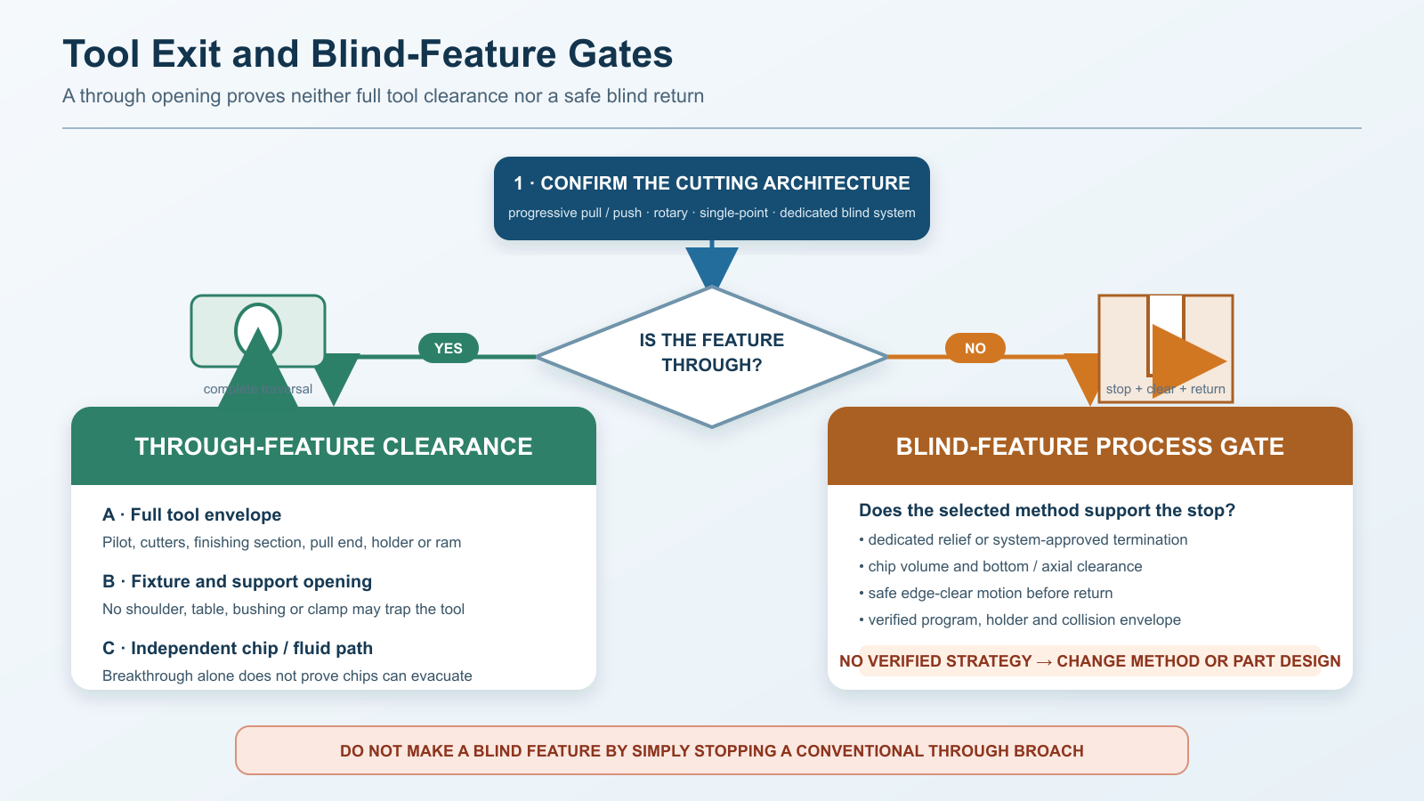
Non-dimensional clearance gates for through and blind features. A blind feature requires a method-specific stop, relief and return strategy; it is not a through setup with a shorter programmed stroke.
Chip exit must also be engineered. Chips may travel with the tool, fall through a support opening, collect in a recess or require flushing and post-process cleaning. Verify that the chosen cutting fluid reaches the cutting zone and that the fixture does not create a chip trap.
Do Not Treat a Blind Feature as a Through Feature
A conventional long progressive broach normally depends on continued travel through the workpiece. Simply stopping it before breakthrough can leave cutting teeth engaged, deny the tool its designed finishing sequence and provide no safe chip or tool exit.
A blind feature requires an approved process architecture. Depending on the feature and equipment, that may involve a dedicated relief, specialized blind-broaching system, rotary method, CNC single-point cycle or another machining process.
For single-point CNC broaching, the program must give the cutting edge room to leave the material before the return stroke. The relief form, stroke endpoint, lateral retraction and chip space are connected. For rotary broaching, bottom clearance and chip accumulation must be reviewed with the tool face and required feature depth. Neither method inherits the exit assumptions of a through pull broach.
그리고 blind keyway broaching guide covers method selection and relief concepts in more depth. Its diagrams are planning aids, not permission to add an unspecified relief to a controlled part.
Prepare the Material Condition, Not Only the Geometry
The tool designer needs the state of the workpiece at the moment of broaching:
- material grade and specification;
- hardness range and heat-treatment condition;
- casting or forging scale and decarburized layer status;
- prior machining method and surface integrity;
- welds, interrupted cuts or inclusions in the cutting path;
- coolant, rust preventive or cleaning residue;
- expected lot-to-lot variation.
Broaching before heat treatment and finishing after heat treatment is a different route from controlled hard broaching. Distortion can move the pre-bore, datum or stock distribution. Do not assume a tool validated on one condition will behave identically after a material or heat-treatment change.
Inspect for burrs at cross-holes and intersecting features. A loose burr can damage an edge or contaminate the fixture; an attached burr can create a local stock spike. Document how parts are cleaned, dried, protected and presented to the machine.

Representative BroachingMach round broaches. This real product photo is not a dimensional preparation standard, a customer project or proof that one tool suits linear, rotary and single-point processes.
Method-Specific Preparation Checklists
Progressive linear pull or push
- Confirm through access for the complete tool, pull end or ram interface.
- Match the prepared opening to the broach pilot and tooth design.
- Control the locating bore, datum face and reaction surface together.
- Check fixture openings for tool and chip clearance.
- Confirm material condition, stock distribution, force and stroke.
- Define safe loading, tool capture and unloading.
For keyway systems using a bushing or shims, verify the exact broach series and documented sequence; see the keyway broach range 그리고 in-house keyway guide.
Rotary broaching
- Use the rotary tool supplier’s pilot and lead specification.
- Confirm internal or external orientation and permitted feature depth.
- Reserve bottom or axial space for the tool and chips.
- Verify holder alignment, spindle condition and work support.
- Validate representative parts at the approved material condition.
CNC single-point broaching
- Control the reference bore and angular datum used by the program.
- Define total stock and the validated increment strategy separately.
- Provide a safe approach and a method-specific end relief when required.
- Confirm the insert clears the cut before the return stroke.
- Check machine-axis rigidity, holder overhang and collision envelope.
- Prove the program at controlled conditions before production release.
Validate with Representative Parts
Preparation is complete only when measured upstream geometry and broaching results correlate. A trial should include normal parts and credible worst-case conditions for bore size, position, hardness and stock.
Record:
- part and drawing revision;
- pre-bore and chamfer measurements;
- datum and support condition;
- material/heat lot;
- broach, holder, fixture and machine IDs;
- cutting-fluid condition;
- force or load trend where available;
- finished-feature inspection and burr/chip observations.
If the result drifts, use the broaching troubleshooting guide to separate preparation, alignment, tooling, machine and fluid causes. Do not compensate for an out-of-control pre-bore by changing an unrelated machine parameter.
RFQ Data for a Part-Preparation Review
Send the controlled drawing and 3D model where available, finished-feature standard, pre-bore process and capability data, material and heat treatment, volume, through/blind condition, entry/exit restrictions, datum scheme, inspection method, available machine, fixture envelope and representative samples.
BroachingMach can then review candidate broach tools and the machine/tooling interface. The result should be a testable preparation and validation plan, not an unsupported universal dimension. Use the 문의 페이지 to provide the application data.
자주 묻는 질문
What size should the pre-bore be for internal broaching?
There is no universal size. It must accept the relevant pilot or tool geometry, leave the stock designed into the cutting process, and meet the required alignment and capability. Obtain the value from the controlled tool-and-part design.
Does every internal broach need an entry chamfer?
Most systems need a controlled entry condition, but its form and size depend on the method, tool and finished feature. Do not apply a rotary-tool chamfer rule to a progressive pull broach or single-point cycle.
How much stock should be left for broaching?
Use the approved prepared and finished geometries to calculate stock, then validate maximum and minimum conditions with the tool, machine and fixture. Extra stock is not automatically safer.
Can a through broach be stopped to make a blind feature?
Not as a general rule. A blind feature needs a process designed for its stop, relief, chip space and safe tool return. Conventional progressive through tooling may require complete passage.
Is tool exit the same as chip clearance?
No. The setup needs both a collision-free path for the tool/holder and a controlled route for chips and fluid. Either can fail even when the nominal hole is through.
What should be checked before releasing production?
Verify the drawing revision, prepared bore and chamfer, datum/support condition, material state, tool and fixture IDs, machine program, chip path and finished-feature inspection on representative parts.
Final Takeaway
Good internal broaching begins upstream. Define the method, drawing, pre-bore, entry, stock, datum, support, tool path and chip path as one system. Keep progressive pull/push, rotary and CNC single-point rules separate, and treat blind geometry as a dedicated process decision. When the preparation plan is tied to controlled drawings and representative trials, the broach is asked to perform the cut it was actually designed to make.


