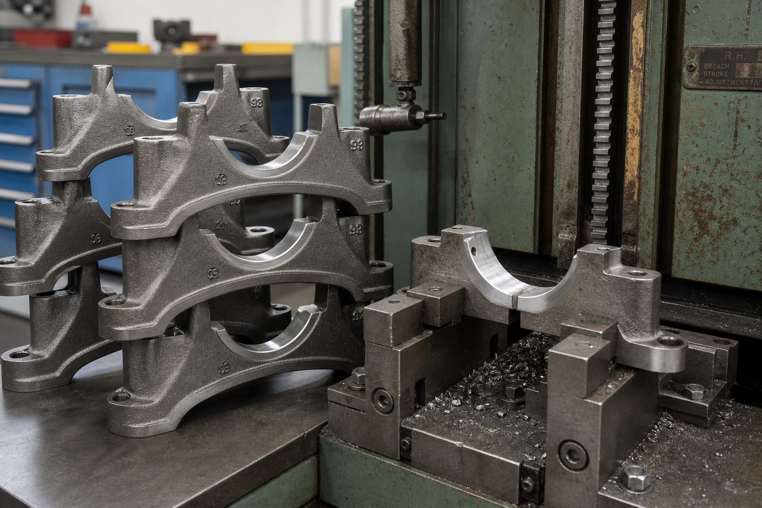
An internal broaching machine pulls or pushes a progressively toothed tool through a prepared opening to produce a keyway, internal spline or other bore profile. This guide helps manufacturing engineers and buyers use the part drawing, prepared blank and tool path to compare machines, specify tooling and plan acceptance checks on sample parts.
목차
- How an Internal Broaching Machine Cuts
- Pilot Hole, Fixture and Part Geometry
- Choosing an Internal Broaching Machine Layout
- Sizing an Internal Broaching Machine
- Proving the Process on Sample Parts
- Questions About Internal Broaching
- Request a Machine and Tooling Review
- References
Key takeaways
- Check the exit clearance with the broach, holder, part and fixture shown on the same drawing.
- Ask the supplier for the force available at cutting speed and the usable travel with the chosen tooling installed.
- Compare quotes using a timed run of accepted parts and agree on the gages before the trial.
How an Internal Broaching Machine Cuts
The IIT Kharagpur NPTEL broaching lesson describes the difference in height between successive cutting teeth as the rise per tooth. This difference gives the tool its feed. As the tool travels, each cutting tooth removes a portion of the stock, and later teeth finish the profile. The size and spacing of the teeth determine how the work is divided over the tool. A speed change alters the rate of travel while the tooth geometry still determines the nominal depth cut by each tooth.
Pull broaching and push broaching
A pull head grips the pull end of the broach, and the tool is loaded in tension during cutting. In the NPTEL tool diagram, the front pilot enters the opening ahead of the cutting teeth. A push broach works in compression. Shorter tools help limit the risk of buckling under this load. For a push application, have the tool designer review the unsupported length, section, guidance and cutting load together. A shallow keyway can still call for careful support when the tool has a slender section.
Tooth pitch sets the distance between adjacent teeth along the tool. For a given workpiece length, it affects how many teeth can be cutting together and how much room each gullet has to carry chips. Discuss the section of the part where the teeth stay engaged longest. That section can drive the tool design even when the feature looks narrow on an end view. For a deeper look at the difference between through-bore work and external profiles, see internal versus external broaching machines.
Pilot Hole, Fixture and Part Geometry
NPTEL's Design for Broached Parts distinguishes a tool passing through an opening from limited-tooth tooling that enters and withdraws from a blind hole. Before specifying a pull-through cycle for an internal broaching machine, check the exit end of the part and the fixture below it. A shoulder, flange or fixture plate can obstruct the cutting teeth, the shank or the pull head. Use a section view that shows both ends of the opening and the tool at the extremes of its travel.
Define the prepared blank
Give the tooling supplier the incoming bore diameter and tolerance, the material condition at the time of broaching and the final profile. The front pilot has to enter the incoming bore, and the cutting teeth need stock to clean up the required surfaces. A drawing that shows only the finished form leaves both requirements open. On a gear blank, include the hub length, wall section and any shoulder that changes access. If stock varies along the bore, show where it varies and how the incoming part will be checked.
Use the final drawing datums to decide which surfaces locate the part and which surfaces carry the axial reaction. For example, when a spline is located relative to an outside diameter, ask how the fixture references that diameter and how inspection will measure the finished relationship. The bore can guide the front pilot while the worktable and fixture support the blank. For a thin hub, include the unclamped part in the inspection plan so the team can check its finished geometry after release.
Match the tool to the feature
| Feature | Information to put on the tooling request |
|---|---|
| Internal spline | Profile and fit requirements, usable tooth length, incoming bore, datum for the spline axis and inspection method |
| Keyway | Slot width and depth, bore size, clocking requirement, entry and exit geometry |
| Square, hexagon or other profile | Across-flats or profile dimensions, permissible corner geometry, orientation to external features |
| Round bore finishing | Incoming diameter, stock distribution, finished size, form tolerance and surface texture |
For a keyway that must line up with another feature, identify that feature and show how the blank can be oriented at loading. If the keyway has an exit relief or terminates near a shoulder, give the supplier a longitudinal view. The internal broaching part preparation guide expands on what to specify for the incoming blank.
Choosing an Internal Broaching Machine Layout
IIT Kharagpur's NPTEL broaching lesson classifies machines by configuration and illustrates horizontal and vertical cutting arrangements. For selection, examine the direction of travel, how the part is presented and the motion needed to generate the profile. These are separate decisions. A vertical machine can use a servo drive, and a helical machine can also have a vertical layout. Compare candidate machines at the actual load and unload positions shown on the arrangement drawing.
| Decision | What to compare |
|---|---|
| Vertical or horizontal | Clearance for the longest tool, access to the fixture, height or floor length, and the path for changing the broach |
| Pull-up or pull-down | Direction of cutting travel relative to the part, where the part is supported, and where the tool can be retrieved |
| Hydraulic or servo drive | Available pull across the required cutting-speed range, how speed is set, what the controls can record, and maintenance access |
| Straight or helical profile | Required relative motion between tool and part, and how any rotary axis is synchronized with axial travel |
| Single or multiple stations | Which loading, cutting, unloading and inspection steps can overlap and which share the same equipment |
For a vertical arrangement, review overhead handling as well as the clearance around and below the table. For a horizontal arrangement, review support for the long tool, the loading height of the workpiece and the clear floor area needed for tool changes. The vertical broaching machine guide 그리고 horizontal broaching machine guide provide layout context for that discussion.
For a helical profile, put the helix hand and angle on the drawing and ask the supplier to explain which assembly rotates during the stroke. The CNC spiral internal broaching machine specifications list pull capacity and rotary torque separately. Ask for both values at the proposed operating conditions and confirm how the control handles the motion between engagement and release. Where the machine will also run straight profiles, include that changeover in the demonstration.
Sizing an Internal Broaching Machine
Ying et al. list a rise per tooth of 0.02 mm at the first tooth and 0.1 mm at a later tooth in their internal spline study. These are entries for the tested tool geometry. They show why a load review needs the complete tooth schedule and the cutting width along the tool. The study models those quantities together to estimate cutting force. Ask for a force estimate for the proposed broach, part length and material condition, followed by a trial on representative blanks.
Check the force and stroke separately
Compare the estimated peak pull with the force available at the planned cutting speed. Ask how the supplier defines its rated pull and how the tool's pull end, holder and fixture are checked for the proposed load. If the job includes more than one stock condition, give the supplier the range and identify the blanks that will be used for acceptance. When adapting an existing internal broaching machine, ask which dimensions of the holder and guides the new tool must fit.
Check the stroke on a drawing of the complete tool and fixture. Include the approach into the pilot hole, travel until the finishing section clears, and the movements needed to release or retrieve the tool. The machine specification can list maximum broach length separately from rated stroke. Check both against the proposed cycle. Include the clearance needed to remove the tool from the enclosure and confirm that a maintenance operator can reach the guides and coolant delivery points.
Compare supplier quotes at the same operating point
Give each supplier the same prepared blank, drawing revision and proposed tool. Ask them to identify the cutting speed used in their force estimate and show where the peak is expected on the stroke. If one quote assumes a different pilot diameter or stock allowance, record the difference before comparing the proposed machine ratings. Have both suppliers show the pull head, support fixture and tool retrieval path on their layout drawings.
If the internal broaching machine will handle a part family, separate the parts that govern the specification. The longest tool can govern clearance while a shorter part with more stock can govern the pull requirement. Ask the supplier to state which part governs each limit and which blanks are included in the acceptance trial. A trial with only the easiest part leaves those limits untested.
Define the full cycle for a capacity quote
Ask for the elapsed time from a repeatable start event to the same event on the next good part. For manual loading, specify where the blank starts, what the operator checks and where the finished part goes. For automatic loading, include orienting, verification, ejection and any waiting on shared handling. Ask the supplier to identify which steps overlap. If parts run on multiple stations, record the output over repeated cycles and specify whether the time includes inspection or periodic tool service. This gives the buyer and supplier a common basis for comparing quotes.
Proving the Process on Sample Parts
Ying et al. measured broaching load with strain gauges and separated a static component from vibration-related variation in the signal. For a production trial, ask what the installed machine actually measures and whether the recorded signal can be exported with its stroke position. Review the location and repeatability of changes in the trace alongside tool inspection and part measurements. A trace can help identify where to investigate a change, while the drawing and gage results determine whether the part is acceptable.
Agree on the acceptance records
- Incoming blank. Record pilot size and material condition for the trial parts. Include representative variation from the intended upstream process.
- Tool and fixture. Record the tool identification, setup and locating surfaces so the run can be repeated. Check that chips can clear the tool and the fixture opening during normal operation.
- Finished feature. Agree on the instruments and drawing datums used to check size, profile, location and any specified surface texture. For a spline, agree on when a functional gage is sufficient and when individual geometry measurements are required.
- Production run. Agree on what constitutes a good part, how long the cycle is observed and what evidence will be retained at the machine handover.
If dimensional results change after a tool change or resharpening, compare parts before and after the change using the same gaging method. Inspect the cutting teeth and seating surfaces before adjusting several setup parameters at once. If a new mark appears at the exit side, check where the part and tool were supported as the finishing teeth cleared. The broaching troubleshooting guide is a starting point for sorting tool, setup and machine checks.
Verify that inspection matches the drawing
On a splined hub, keep the fit check separate from the inspection of the spline's location relative to its datum. A mating shaft or functional gage can be useful for an assembly check. Where the drawing also controls the relationship between the spline and an outer bearing seat, record that relationship with the agreed datum setup. If a roughness requirement applies to a particular flank or bore surface, mark the measurement location on the drawing before the trial. Include that location and the gage identification on the acceptance record so a later production check can repeat the measurement.
Questions About Internal Broaching
Can an existing internal broaching machine run a new spline family?
Give the tooling supplier the current pull head and guide drawings, worktable opening, available cutting travel and part envelope. Ask for a setup drawing that identifies which fixtures or adapters must change. Include the changeover and the first accepted part in a trial if the machine will run several families in the same shift.
When should the blank be heat treated?
State the material condition at broaching and at final inspection. If heat treatment follows cutting, agree on which measurements must be repeated afterwards and how the trial will represent the final process sequence. If the material arrives hardened, give the tool supplier the specified hardness range before a cutting tool is selected.
What should be specified for coolant and chip collection?
Ask the machine and tooling suppliers to identify the fluid, how it reaches the cutting zone and how it returns from the fixture. Include chip collection access in the layout review. During the trial, inspect the gullets, part surfaces and collection area after repeated cycles, and record any cleaning needed to sustain the quoted cycle.
Request a Machine and Tooling Review
To specify an internal broaching machine, send the finished part drawing, prepared blank drawing, material condition and target production rate. Include the longest part and any geometry that blocks access to the bore. If the job will use an existing line, include the loading orientation, available clearance and the gages that will be used at acceptance. These inputs let the supplier review the broach, machine travel, fixture and trial together. Contact BroachingMach to request a review of the proposed process and sample-part acceptance plan.
References
- Broaching — IIT Kharagpur NPTEL lesson — Tool geometry, rise per tooth, guidance and machine arrangements.
- Design for Broached Parts — NPTEL guidance on through and blind internal features.
- Numerical and experimental investigations on cutting force of broaching internal spline holes — Ying et al. report tool geometry, cutting-force measurements and signal processing.