
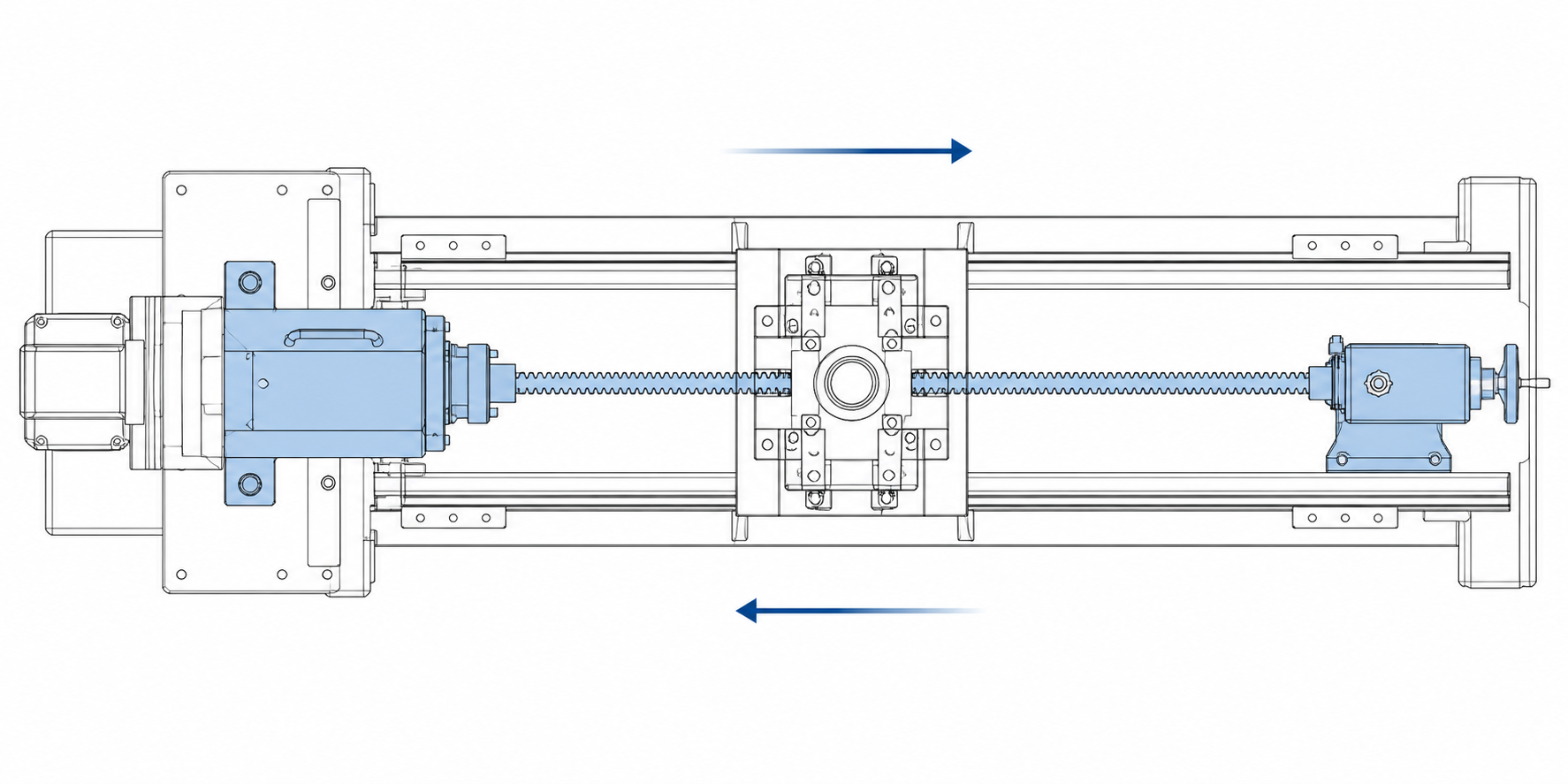
A horizontal broaching machine cuts internal or external forms by driving a multi-tooth broach through or past the workpiece in a horizontal stroke. The ram slides along a level bed, the broach travels parallel to the floor, and every tooth in the rising stack removes its slice of stock until the finished feature — a long spline, a deep keyway, a contoured surface — is complete in one pass. For plants machining large castings, long shafts, and heavy driveline components, the horizontal layout is often the only configuration that fits the part, the tooling, and the line at once.
This guide covers how the machine works, how it compares with vertical broaching, machine types, part selection, machine structure, the specification checklist, automation, and applications. If you are new to the process, start with our primer on what horizontal broaching is; this article assumes the basics and focuses on selecting and deploying the machine.
What Is a Horizontal Broaching Machine?
A horizontal broaching machine is a machine tool whose cutting motion — the stroke of the ram and the travel of the broach — runs along a horizontal axis at working height, on a bed sitting directly on the shop floor. The workpiece is fixtured stationary, and the broach, gripped by the ram’s coupling, passes through the part (internal broaching) or across its exterior (surface broaching) in a single linear cut. Because the axis is level, gravity works with the process: heavy parts rest on horizontal locators, long broaches are supported along their length, and loading equipment reaches the part from above with cranes, gantries, or rollers.
Machine-tool reference practice classifies horizontal broaching machines as designed for three duties: pull broaching, in which the broach is pulled through the workpiece (the dominant method for internal work, since a pulled broach is in tension and cannot buckle); surface broaching, in which the tool shears stock from an external face; and continuous broaching, in which fixtured parts ride a chain or track past stationary broaches without stopping. Most horizontal machines on shop floors are pull-type internal machines, but the same bed-and-ram architecture serves surface and continuous duty.
The category earns its place on two strengths. First, stroke: because the bed extends along the floor rather than up into the building structure, a horizontal machine can carry broaches and deliver strokes impractical to hang or bury vertically. Second, part access: the work zone is open at both ends and from above, so heavy workpieces load with standard material handling. Both strengths matter more as the part gets bigger — which is why horizontal machines dominate the large end of the broaching range.
How the Machine Works: One Stroke, Start to Finish
An internal pull cut proceeds in a fixed sequence. The workpiece is placed in the fixture with a pre-machined pilot hole aligned on the stroke axis. The broach — long, slender, and threaded with progressive teeth — is introduced to the pilot hole, the ram’s coupling engages its pull end, and the ram draws the full length of the tool through the part. Each successive tooth stands slightly taller or wider than the last, so each slices a thin, controlled chip; the rear finishing teeth cut at final size and set the surface finish. The part is unloaded, the ram returns at rapid traverse, and the cycle repeats.
Surface work follows the same stroke logic with the tooling inverted: the broach passes across the clamped part’s exterior. The cutting physics are identical — progressive teeth, rising stock removal, one-pass completion — but the fixture, not a pilot hole, must locate the part and react the full cutting force.
Two practical details shape daily operation. Stroke length is not the same as cut length: the ram must pull the entire broach clear of the work, so a short feature cut with a long broach still needs a long stroke. And broach handling is part of the cycle: internal broaches are heavy precision tools, so well-equipped machines use lifters, rollers, or support arms to carry the free end of the tool, protecting teeth and operator alike.
Horizontal vs. Vertical Broaching: The Modern Comparison
The horizontal-versus-vertical question is the first fork in every broaching project. Both configurations cut the same forms with the same tools — the decision is driven by part size, floor space, loading logistics, and line integration, not cutting capability. We maintain a dedicated article on the difference between horizontal and vertical broaching machines; here is the comparison at selection depth.
| Selection factor | Horizontal machine | Vertical machine |
|---|---|---|
| Floor space | Long, low footprint — bed length scales with stroke and broach length; height stays modest | Compact footprint per unit of stroke; height scales with stroke, and some designs need overhead clearance or a pit |
| Stroke ceiling | Practically unlimited — beds extend to carry multi-meter broaches for long splines and deep slots | Stroke is bounded by building height or pit depth; very long broaches become awkward to hang and support |
| Part loading | Heavy parts load at working height with cranes, hoists, or rollers from above — the natural direction for heavy castings | Parts load onto a fixture table, easy for small and medium parts; very heavy parts need careful lift planning |
| Chip and coolant handling | Chips travel along the bed; well-designed beds slope or conveyor chips away at the work zone, but flushing must be engineered | Gravity pulls chips and coolant down and away from the cut continuously — a structural advantage for cleanliness |
| Long-part support | Long workpieces lie on supports along the bed; deflection control is straightforward | Long parts must cantilever or be staged vertically, which complicates fixturing |
| Automation pattern | Suits in-line flow: parts arrive on conveyors, get broached, and leave in a straight production line | Suits turret and shuttle patterns: indexing tables let stations load, broach, and unload in overlapping time |
Read the table with your part in hand and the decision usually makes itself. Steering knuckles and chassis castings favor horizontal loading logistics; small levers, forks, and pump components favor the compact footprint and turret automation of the vertical layout. For the other configuration at the same depth, see our vertical broaching machine complete guide — many plants run both, each assigned to the parts it handles best.
Types of Horizontal Broaching Machines
Horizontal internal broaching machines are the backbone of the category. The workpiece is fixtured at the head of the bed, and the ram pulls a broach through the pilot hole along the bed axis — the standard machine for internal keyways, splines and serrations, polygon bores, and shaped holes in gears, sprockets, hubs, pulleys, and pump components. Because pull broaching puts the tool in tension, the long slender broaches needed for deep bores and long splines are safest on this layout. Our horizontal internal broaching machine page details the configuration, and the full range is on our horizontal broaching machine product pages. The same layout stretches to its extreme for long tubes and barrels — features deep inside a bore many diameters long; our barrel broaching case covers that end of the range.
Horizontal surface broaching machines mount the broach on the ram and pass it across the exterior of a clamped part — flats, steps, dovetails, and contours on parts too large or too long for a vertical envelope. Long beds make the layout the natural home for constant-section forms: racks, long pads, and profiles that run the length of a casting. The horizontal machine takes the jobs where part length, loading direction, or line layout says level rather than upright.
Continuous (chain-type) broaching machines are the throughput extreme of the horizontal idea: the broaches stay fixed while fixtured workpieces ride an endless chain track past them, so loading and unloading overlap cutting and the line never idles. Small- and medium-sized parts in very high volume — lever forks, link ends, small pads and flats — are the classic workload. The chain layout turns the horizontal machine’s historic weakness (footprint) into a strength: one continuous machine replaces a battery of single-stroke machines. See our continuous broaching machine article for the full treatment.
Which Parts Belong on a Horizontal Machine?
Three part profiles point to the horizontal layout.
Parts that need long strokes. Long internal splines, deep keyways, and multi-diameter bores demand long broaches, and a long broach demands a long travel envelope. When the tool needed for the feature pushes past what a vertical machine can hang and support, the horizontal bed is the answer: the broach lies along its whole length, supported and guided.
Large, heavy workpieces. Chassis and suspension castings — steering knuckles, control arms, crossmembers — are awkward to stage vertically but natural to handle lying flat. On a horizontal machine the part rests on level locators, the cutting force presses it into its seat, and overhead cranes or roller conveyors deliver and retrieve it in the direction heavy parts prefer to move.
Parts that feed a horizontal line. Where parts flow through a transfer line at a fixed height — as in most automotive driveline and chassis lines — a horizontal machine accepts the part from the conveyor, cuts it, and passes it on without a vertical lift. That motion saved, multiplied by full part volume, is real money.
Machine Structure: Bed, Ways, Ram and Broach Handling
A horizontal broaching machine is built around four structural elements whose quality determines everything the machine will hold.
The bed and ways. The bed is a long, rigid base — commonly a ribbed casting or welded structure — carrying the guide ways for the ram along the full stroke. Bed rigidity sets the ceiling on accuracy: under full cutting force the ways must hold the ram’s path straight, because any bow in its travel prints directly into the part. On internal work the bed carries the pull force without distortion; on surface work, the ways are the tool path itself.
The ram (main slide). The ram grips and moves the broach. Hydraulic rams remain the industry standard for smooth, controllable force at heavy loads; servo-driven slides appear where programmable stroke profiles justify them. The ram carries the full pulling force of the cut — rated from a few tons on small internal machines to many tens of tons on large production machines — and transmits it into the bed through the ways.
The broach coupling and quick-change head. The coupling at the ram face grips the broach’s pull end. Production machines increasingly use quick-change couplings, so the broach swaps between jobs in minutes without re-establishing alignment — essential where one machine runs several part numbers. Starter fixtures and pilot bushings follow the same changeover logic.
Work support and broach support. Work supports and tail-type backstops brace the fixture against pull-off forces; broach lifters, rollers, and cradles carry the free length of the tool during entry, cutting, and return, keeping long broaches from sagging or nicking in handling. Around the core elements sit coolant, chip conveyor, and guarding — chip management along a horizontal bed is an engineering item, not an afterthought.
How to Specify a Horizontal Broaching Machine
Specification is a sequence; work through these four parameters in order and the machine defines itself.
1. Stroke. Start from the part: the cut length, plus the broach’s approach and pull-off clearances, plus room to unload the finished part from the tool. The honest number is driven by broach length, not feature length. Under-specifying stroke is the classic first-time buyer’s error: a machine that just fits today has no room for tomorrow’s longer broach.
2. Force (tonnage). The machine must pull the worst-case broach through the worst-case material at productive speed. Force follows from chip width, rise per tooth, teeth cutting simultaneously, workpiece material, and bluntness at regrind time — not from a rule of thumb. We walk through the math in how to calculate broaching machine tonnage; run it before you shop, because force capacity is the most expensive thing to get wrong.
3. Broach length accommodation. Beyond stroke, the machine must physically accept the tool: coupling height and bed length must hold the full broach, pull end and starting pilot included, through the complete travel. Long-spline and deep-bore parts carry broaches measured in meters — confirm the envelope against the tool drawing, not the part drawing.
4. Loading direction and workholding. Decide how the part arrives: by crane from above, by roller from the side, by robot, or by hand. The loading answer sets fixture height, guard openings, and the automation interface — and it closes the loop on the layout question: if your handling answer is an overhead crane at working height, the machine answer is horizontal. For the full decision framework, see our guide on how to choose the right broaching machine.
Cycle Time and Automation: In-Line Flow vs. Turret Indexing
The two configurations automate differently. Vertical machines automate by indexing: a rotary or shuttle table presents fixtures to the cut in overlapping succession — while one station broaches, another unloads and reloads. Horizontal machines automate by flowing: the part enters at one end, is broached in position, and exits toward the next operation, in line with the conveyor logic of a transfer line.
Neither pattern is universally faster; each wins in its setting. Turret indexing maximizes utilization on compact footprints and suits small-to-medium parts at high volume. In-line flow suits large parts and integrated lines: a horizontal broaching station drops into a machining line as just another step, at the same handling height and with no vertical motion. For chassis castings that already travel by roller or overhead handling, it can be the only pattern that fits without re-planning the material flow.
Continuous chain machines take the in-line idea to its limit: loading, cutting, and unloading all happen at once, and throughput is set by chain speed rather than stroke cycle. That is the structure to reach for when part volume, not part size, is the challenge.
Typical Applications
The workload that keeps horizontal broaching machines in production worldwide concentrates in a handful of part families:
- Steering knuckles and chassis castings. Contoured pads, flats, and bracket faces on large suspension components — classic horizontal surface work, where part size and loading direction match the layout.
- Connecting rods. Parting faces, bolt seats, and bore-adjacent features on rods are broached in volume; our connecting rod broaching case study follows a real production sequence.
- External spline shafts. Long involute and straight-sided splines on transmission and driveline shafts demand broaches and strokes that only a long bed accommodates.
- Gears, sprockets, and hubs with internal forms. Internal splines, keyways, and polygon bores in medium-sized rotational components are the daily bread of internal machines.
- Pump and compressor components. Keyseats and shaped bores in housings and rotors, where one-pass sizing keeps bore-to-feature relationships consistent across the batch.
- High-volume small parts on continuous chains. Lever forks, link ends, and small flats and pads — parts whose volume, more than their size, calls for the never-idle chain layout.
Across the list the pattern holds: broaching is a volume process, and the horizontal machine is the volume answer where the part is long, heavy, or in-line fed. When volumes are moderate or the part is small, the same features often migrate to vertical machines — the two layouts are complements, not competitors.
자주 묻는 질문
When should I choose a horizontal broaching machine over a vertical one?
Choose horizontal when any of three conditions holds: the part needs a broach or stroke longer than a vertical envelope can support; the workpiece is heavy and loads naturally from above; or the operation must sit in-line in a horizontal material flow. Choose vertical when the part is small-to-medium, floor space is tight, and turret indexing automation fits your volume. The cutting results are equivalent — the decision is logistical, not metallurgical.
What parts are best suited to horizontal broaching?
The core families are long spline shafts and parts with deep internal forms (long-stroke internal work), large chassis castings such as steering knuckles and control arms (heavy parts, horizontal loading), connecting rods in production volume, and gears, hubs, and pump components with internal splines or keyways. Very high volumes of small parts are often better served by continuous chain machines — themselves a horizontal layout.
How much stroke do I need?
Stroke is set by the broach, not the feature: the ram must pull the entire broach — starting pilot, cutting length, and pull end — completely clear of the workpiece. Calculate from the tool drawing as cut length plus approach and pull-off clearances, then add margin for part unloading and future broach revisions. And verify that bed and coupling accommodate the full broach through its travel, since stroke alone does not guarantee tool clearance.
How much floor space does a horizontal broaching machine need?
Plan for a long, low footprint: overall length runs to the full stroke plus broach accommodation, coupling, and return-end space — then add working clearance at the loading end, broach handling room alongside, and maintenance access along both sides. Width stays modest — the layout trades floor area for building height, so where a vertical machine grows upward (or down into a pit), a horizontal machine grows along the aisle. Lay out the full envelope, including the broach in its handling equipment, before committing to a floor-plan spot.
Selecting Your Horizontal Broaching Machine
The horizontal broaching machine is the right tool when the part is long, heavy, or in-line fed — when the broach needs a bed, the workpiece needs level support, or the line needs a station parts flow straight through. Specify in sequence — stroke, force, broach accommodation, loading direction — and the machine that emerges will hold its accuracy and cycle time for the life of the part program.
As a builder of horizontal broaching machines for internal, surface, and continuous work, we configure machines around customers’ parts rather than the reverse. Explore our horizontal broaching machine product pages, and if you have a part print and an annual volume, send them to our engineering team — we will review the feature, recommend configuration and stroke, run the force calculation with you, and quote machine and broach as one package.


