
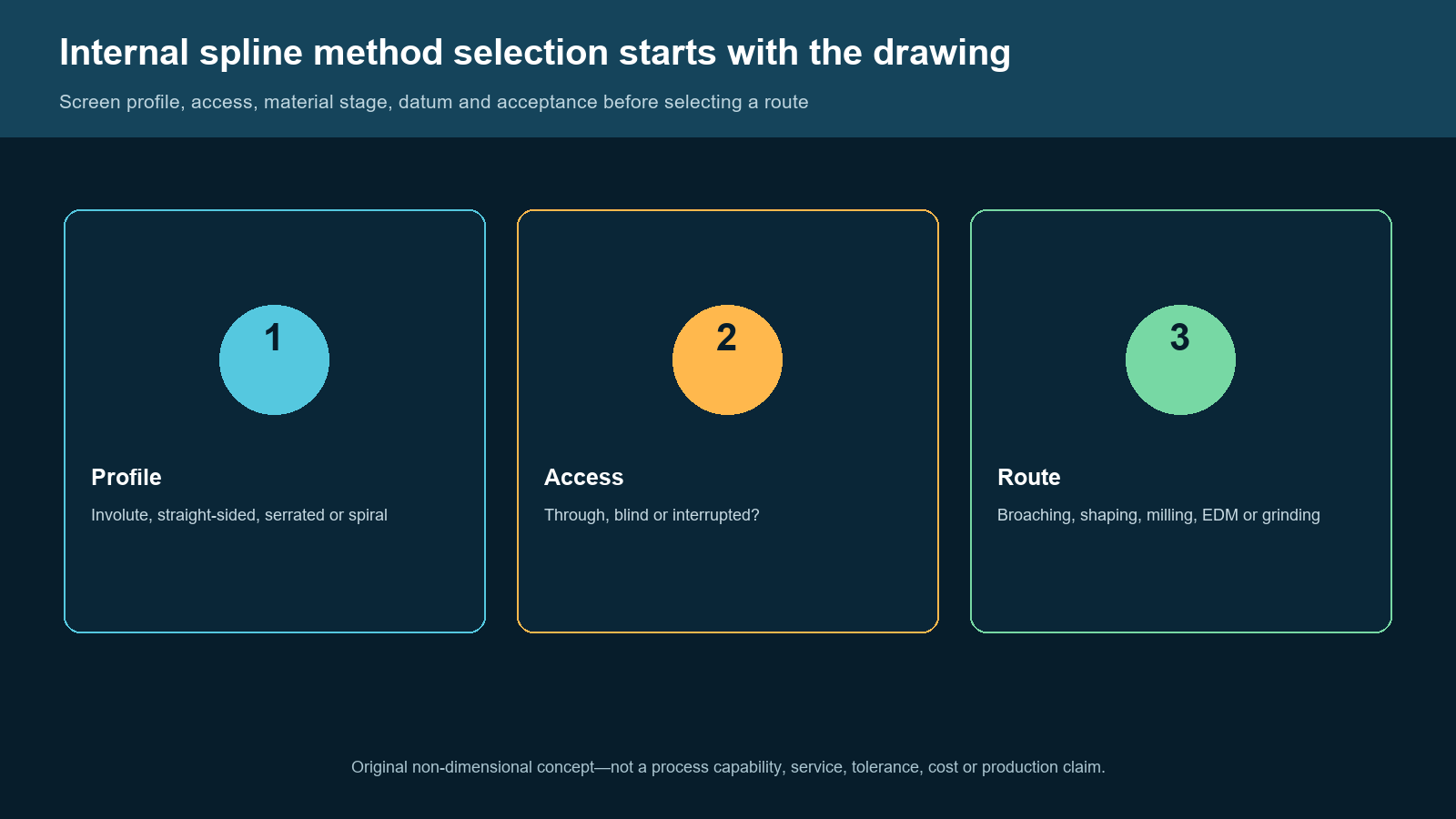
Original non-dimensional engineering concept. It is not a customer part, a machine photograph, a production result or a claim that BroachingMach supplies every method shown.
An internal spline is not selected by naming a process first. It is selected by reading the profile, access, blank condition, material stage, functional datum and acceptance requirement as one system. Broaching, shaping, milling, EDM and grinding can appear in internal-spline discussions, but they do not solve the same geometry under the same conditions.
A progressive broaching route is evaluated around a prepared opening, tool entry and guidance, chip space, full travel, fixture support and a stable released profile. A shaping or milling route is evaluated around cutter access, motion and support. EDM routes depend on a conductive workpiece and a valid wire or electrode approach. Grinding is a different process family whose application must be reviewed against the exact profile and material condition. None is automatically the “best” method from the word spline alone.
This is a neutral drawing-led selection framework. It does not convert competitor pages or any public equipment listing into a service commitment, tolerance, capacity, cost, output or inspection result. BroachingMach-specific language is limited to a potential broaching-route review from the controlled drawing.
The Short Answer
This page screens a specified production feature only. It does not provide repair/remachining instructions, process parameters, supplier comparisons or production results.
Start the review by asking five questions:
- What internal spline form is released: involute, straight-sided, serrated, spiral or another defined profile?
- Is the feature through, blind or interrupted, and what actual tool approach and exit are available?
- What is the blank condition and material stage when the internal teeth must be made?
- Which bore, face, axis or mating feature is the functional datum?
- How will the finished spline be accepted: functional fit, analytical measurement, or both?
When the profile and access are defined, a broaching route may be one candidate to evaluate. If the drawing raises access, end-condition, material or finishing questions, ask the responsible providers to compare the relevant method families. The choice must be validated against the controlled drawing and responsible process provider.
For spline-broaching fundamentals, types, preparation and common process risks, see Spline Broaching: The Complete Guide. This article does not repeat that guide; it screens whether progressive broaching is the right method family before a detailed route is developed.
Start With the Internal Spline Definition
An internal spline is a relationship between multiple teeth and the part's functional reference—not merely a non-round hole. The review should identify the form standard or controlled geometry, tooth count, engagement length, lead/spiral condition where applicable, minor/major/pitch relationships as defined on the drawing, end conditions and protected features.

The access map identifies geometry questions only. It does not determine a method, tolerance, cycle time, cost or process capability.
Through internal splines
A through feature can create a potential path for a conventional progressive broach, provided the opening, guidance, tool connection, full travel, chip clearance, workpiece support and exit conditions are reviewed. A through condition can also be relevant to other methods, but it does not automatically make every route practical.
Blind internal splines
A blind end condition changes the selection problem. A conventional progressive route may require special relief, retraction, chip-control and tool-geometry review. A shaping, EDM or other route has its own approach, clearance, holding and termination questions. Treat the end condition as a primary drawing input instead of treating the feature as a shortened through spline.
Interrupted or constrained splines
Cross holes, shoulder faces, thin walls, nearby finished surfaces, partial teeth and obstructed zones can constrain a tool path. Record them directly on the drawing review. A candidate route must preserve protected areas and maintain sufficient support; a generic spline label cannot answer that question.
Method Families: What Each One Must Prove
The following table is not a list of universal preferences. It identifies the question each method family must answer before it is selected.
| Method family | What it may be considered for | What the drawing review must establish |
|---|---|---|
| Progressive broaching | A stable internal profile with a compatible prepared opening and path | Entry, guidance, tooth travel, chip route, exit/return, fixture/load path and acceptance plan |
| Shaping / slotting-type route | Access-limited or route-specific internal profiles | Tool motion, clearance, end condition, holding, datum transfer and route-specific inspection |
| Milling route | A cutter-access route where support and reach can be validated | Cutter reach, overhang, tool path, chip evacuation, workholding and profile/datum verification |
| EDM route | Conductive material with a valid wire or electrode approach | Conductivity, wire/electrode access, approach, flushing/holding, protected zones and acceptance plan |
| Grinding route | A profile/material/finish route requiring a dedicated grinding review | Profile definition, material stage, wheel/process route, holding, datum and inspection strategy |

Screening aid only. It does not rank methods or imply that BroachingMach offers every method or can achieve a specified result.
Progressive broaching
Progressive broaching generates the profile through a sequence of teeth. The tool, part opening, guide, fixture, machine path and chip route form a single system. This can be a useful route to assess when the profile is released and stable, the part allows a suitable entry and travel path, and the engineering team can define the datum and acceptance method.
It is not enough to compare a broach with another method by an assumed production quantity or a generic cost chart. A change in form, material stage, feature length, access, bore relation, heat-treatment sequence or inspection requirement can change the tool and process review.
Shaping and milling
Shaping or slotting-style routes use a different tool motion from progressive broaching. Milling introduces cutter reach, overhang, programming, chip evacuation and support questions. Both may be considered in the wider industry for particular parts, but a site article must not claim that BroachingMach supplies them simply because they appear in a comparison SERP.
Use the method family as a screening label. The provider responsible for the actual alternative route must validate reach, holding, tool path, material stage and acceptance against the released part.
EDM
If EDM remains a candidate, ask its provider to confirm material eligibility, approach, holding, protected zones and acceptance requirements against the drawing. This article does not define EDM eligibility or performance.
Do not infer an EDM service offer from an equipment category or a competitor page. Confirm the commercial and engineering route directly with the responsible provider.
Grinding
Grinding is not a catch-all answer for every spline. The released profile, material state, access, holding, datum and inspection plan determine which grinding questions the responsible provider must answer. This article does not establish a workpiece envelope, process sequence or measured outcome.
Datum and Fixture Questions Cannot Be Added Later
An internal spline often works with a mating shaft, coupling, gear or hub. The functional question may be torque transfer, indexing, axial location, sliding engagement or another drawing-defined relationship. Identify the reference bore, face, axis or mating feature before choosing the process.
For a broaching route, the fixture must support the part, resist unintended movement and allow the required tool travel and chip clearance. The guide or bushing, pull or push connection, workpiece location and load path require engineering review. A competitor fixture page or a generic drawing does not prove that a specific fixture has been designed, built or validated for this part.
For alternative routes, holding and datum transfer remain essential. The process may change, but the functional reference does not disappear. Make the relationship explicit in the controlled drawing review.
Inspection Is a Selection Gate, Not a Final Afterthought
The inspection plan should say what must be known after the feature is made and how it relates to the functional datum. An internal spline may require a functional check, an analytical profile evaluation, or a combination. The right approach depends on the feature class, access, production stage and drawing requirements.
Do not assume one plug, pin, gage or CMM routine fits every spline. The published BroachingMach inspection inventory includes equipment categories relevant to dimensional, profile, material and flaw-detection checks, but that does not prove a named instrument or check is used for every job. The part-specific acceptance plan must control the decision.
A Controlled-Drawing Review Sequence

Original planning checklist. It is not a quote, machining instruction, process qualification or production approval.
- Freeze the profile definition. Identify the form, teeth, lead/spiral condition, end condition and protected zones from the controlled drawing.
- Record the blank and material stage. State the opening, material callout, heat-treatment condition and any preceding features.
- Classify access. Mark through, blind or interrupted conditions, plus all shoulders, cross holes, thin walls and obstructions.
- Mark the functional datum. Connect the spline to the bore, face, axis or mating relationship it must preserve.
- Screen the method family. Ask each responsible provider to review its path, access, material inputs, fixture and acceptance requirements against the released drawing.
- Define acceptance before release. Decide what functional and/or analytical verification is required and validate the route with the responsible provider.
Common Errors in Internal Spline Method Selection
Treating every spline as a through-broach job
Feature access, end condition and obstacles can rule out a conventional progressive path. A blind or interrupted feature needs a dedicated review; it cannot be approved from a generic spline description.
Using a production-volume assumption as the complete decision
Profile stability and production planning matter, but they do not replace a check of access, material stage, datum, fixture and inspection. Avoid presenting generic cost or cycle-time claims as if they select a route for every part.
Releasing a route before design changes are controlled
A revision to tooth form, end condition, material stage, bore relationship or inspection requirement can change the route review. Keep the drawing revision, acceptance question and process discussion connected rather than assuming an earlier method decision remains valid.
Treating an equipment list as a service promise
Public equipment lists support only the categories actually stated. They do not establish a capability for every geometry, material, size, tolerance, inspection method or production service. Confirm the actual project scope before making commercial or technical commitments.
Copying another supplier's tolerances or results
Competitor pages can reveal what users search for and how a decision is structured. They cannot prove BroachingMach's tolerance, capacity, tooling, fixture, alternative-process service or customer result. Use the released drawing and first-party evidence instead.
When to Request a Broaching-Route Review
Send BroachingMach a controlled drawing when you want to determine whether a progressive internal-spline route is appropriate. Include the profile definition, through/blind/interrupted condition, material and heat-treatment stage, starting opening, functional datums, required acceptance method, anticipated design changes and relevant fixture context.
If shaping, milling, EDM or grinding is under consideration, have the provider responsible for that method validate the route against the same drawing. The purpose of this framework is to make the decision inputs visible before a process commitment—not to claim a universal winner.
Related Reading
- Spline Broaching: The Complete Guide
- Transmission Gear Internal Spline Broaching
- Hard Broaching vs Soft Broaching
- Complete Guide to Broaches
- How to Choose the Right Broaching Machine
FAQ
What is the best method for machining internal splines?
There is no universal best method. Start with the released profile, access, blank, material stage, functional datum and inspection plan; then validate the actual route with the responsible engineering provider.
Can internal splines be broached?
They can be evaluated for a progressive broaching route when the profile, prepared opening, entry, guidance, travel, chip path, fixture and acceptance conditions are compatible. The actual part must be reviewed.
Can EDM be used for internal splines?
EDM may be considered for a conductive workpiece with a valid wire or electrode approach. It still requires route-specific holding, protected-zone and acceptance review.
What information should be supplied for an internal-spline review?
Provide the controlled drawing, profile definition, access/end condition, starting opening, material stage, functional datum, fixture context and drawing-led acceptance requirement.


