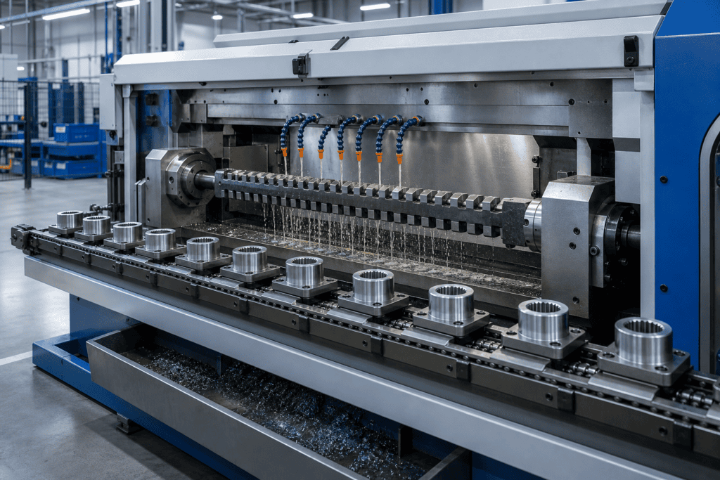
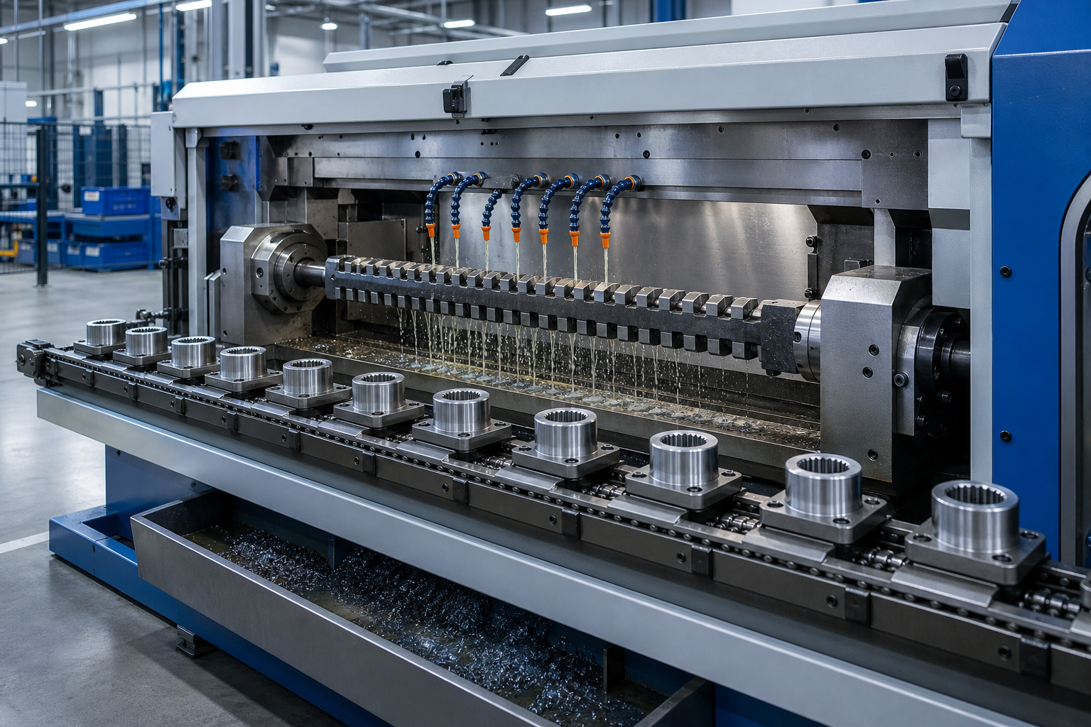
Conceptual illustration of a continuous broaching line with workpieces moving past a stationary cutting zone. It is not a photograph or dimensional representation of a BroachingMach product.
A continuous broaching machine moves a sequence of workpieces through a cutting zone without using a separate cutting stroke and return stroke for every part. In the common arrangement, the broach remains stationary while chain-mounted fixtures or a rotating carrier table moves the parts past its progressively cutting teeth.
The concept is attractive for repetitive, high-volume production because loading, transport and cutting can overlap. However, “continuous” does not automatically mean faster or more accurate for every component. The economics depend on part access, fixture pitch, cutting length, tool engagement, loading automation, chip control, changeover frequency and required quality.
This guide explains the working principle, chain and rotary-table configurations, the difference from rotary broaching, and the engineering questions to answer before selecting a machine.
What Is a Continuous Broaching Machine?
Broaching is a machining process in which a multi-tooth tool removes material in a controlled sequence. Each successive tooth normally cuts slightly deeper than the one before it. If you need the general process first, see our guide to what broaching is.
In a conventional reciprocating machine, the broach travels through or across one workpiece during the cutting stroke, then the system unloads, resets or returns for the next cycle. In continuous broaching, a carrier system presents multiple workpieces to a fixed cutting station in sequence.
The word describes the flow of workpieces through the machine, not an infinitely long broach or an uninterrupted cut on one part. Individual parts still enter and leave the cutting zone. The production advantage comes from organizing those events into a repeating line rather than resetting the entire cutting axis for every component.
Continuous machines are most often associated with surface and open-ended operations where the fixture can carry the part past a stationary broach. Internal applications require suitable through-access, alignment and a machine concept designed for the tool/workpiece relationship.
How Continuous Broaching Works
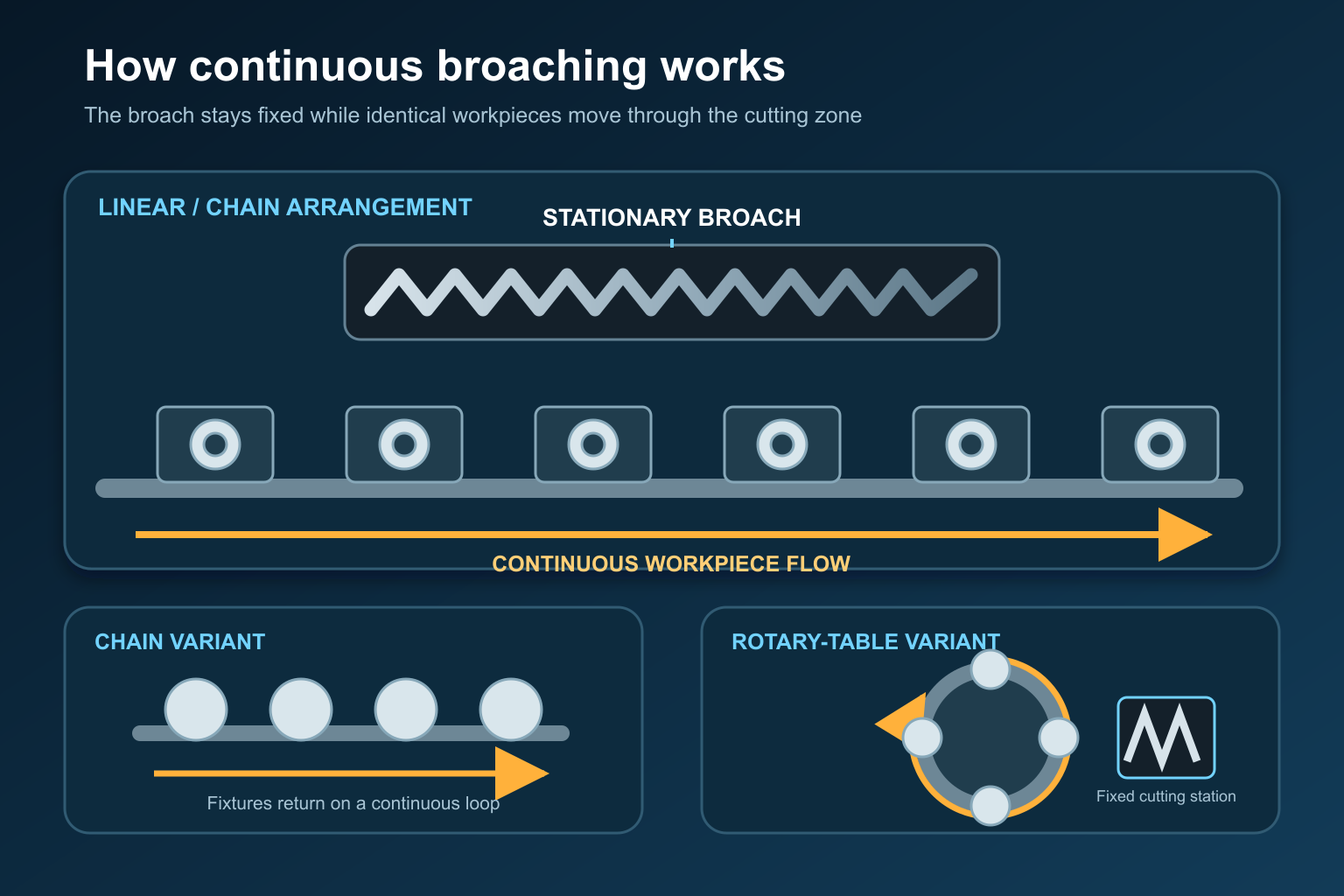
A stationary broach cuts sequential workpieces carried through the cutting zone. The carrier path may be linear/chain-based or circular around a rotary table.
A typical cycle can be understood in six stages:
- Load. An operator or automation places each blank in a dedicated fixture or carrier.
- Locate and clamp. The fixture controls the cutting datum and resists broaching force.
- Approach. The carrier brings the part into the entry section of the stationary broach.
- Progressive cutting. Successive broach teeth remove the planned stock as the carrier moves through the cutting zone.
- Exit and inspect. The finished feature clears the tool; gauging may occur in-line or off-line.
- Unload and return the carrier. The empty fixture travels back to the loading position while other fixtures continue moving through the process.
Carrier speed is only one part of cycle time. Fixture pitch determines how closely parts can follow one another. The required cutting length, number of simultaneously engaged teeth, load/unload time and safe spacing all influence practical output.
The fixture and broach must keep the cutting path aligned under load. Any pitch error, carrier wear, loose clamping or contamination at the datum can repeat across many parts before an operator notices it. Continuous production therefore needs planned force monitoring, gauging and tool-condition checks—not just a fast conveyor.
Main Continuous Broaching Machine Types
Continuous-Chain Broaching Machine
A continuous-chain machine uses a loop of linked carriers driven around sprockets or another guided track. Workpieces are loaded into fixtures, travel through a straight cutting zone and later return to the loading station.
This layout is useful when many similar parts require an accessible surface, slot or open-ended profile. A long horizontal bed can provide room for loading, cutting, inspection and unloading stations. Multiple fixtures also make automatic part handling possible.
Chain systems introduce their own engineering limits. Link wear, pitch variation, carrier guidance and accumulated positioning error must stay compatible with the required feature. The fixtures also need enough stiffness to resist the force without lifting, twisting or allowing chips beneath the locating surfaces.
Rotary-Table Continuous Broaching Machine
A rotary-table arrangement places fixtures around a circular indexing or continuously rotating carrier. Parts move around the table and pass one or more fixed working stations. The circular layout can reduce floor length and make loading, cutting, gauging and unloading accessible around one platform.
Some machines move continuously; others use controlled indexing between stations. The term should therefore be checked against the actual mechanism rather than assumed from a sales label. For any proposed machine, confirm whether cutting occurs during constant table motion, during an indexed dwell, or through a separate broach stroke.
Rotary-table layouts can be effective when the part is compact, fixture loading is repeatable and station integration matters. Available table diameter, number of fixtures, tool access, chip fall, guarding and maintenance access constrain the final design.
Rotary-Table Continuous Broaching Is Not Rotary Broaching
These terms are easy to confuse:
- In a rotary-table continuous machine, the table carries multiple workpieces through a stationary broaching station. Circular travel organizes production.
- In rotary or wobble broaching, a broach and workpiece rotate relative to one another, usually with a small angular offset, to generate a polygon or similar form.
The first is a machine-flow arrangement; the second is a distinct cutting method. When requesting equipment, describe the feature, cutting action and carrier movement rather than using “rotary broaching machine” alone.
Continuous vs Reciprocating Broaching Machines
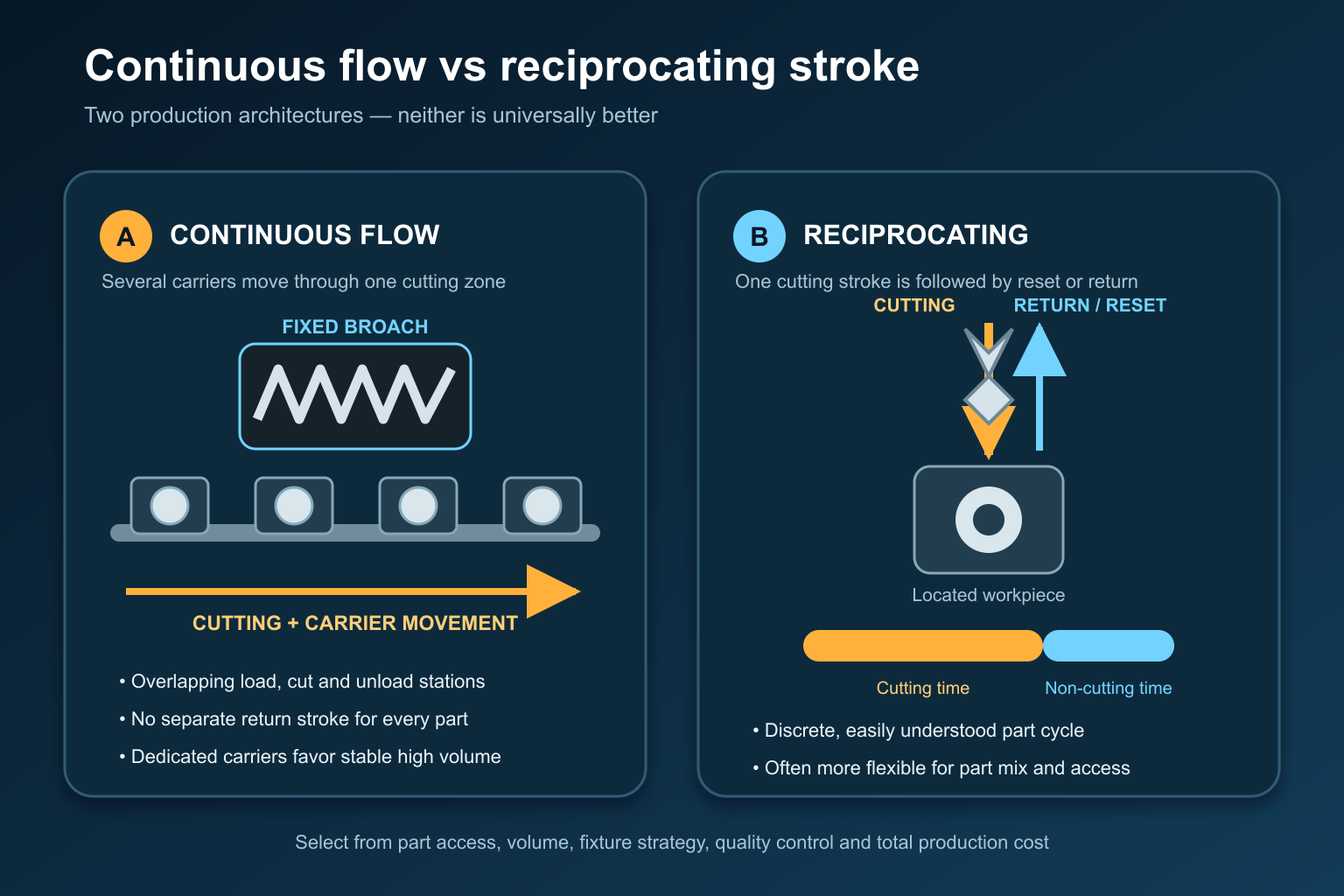
Continuous broaching overlaps carrier movement and cutting. A reciprocating machine completes a cutting stroke and then resets or returns before the next part.
| Decision factor | Continuous broaching | Reciprocating broaching |
|---|---|---|
| Primary motion | Multiple workpieces move past a cutting station | Broach moves through/across a located workpiece, or the workpiece moves through one stroke |
| Production pattern | Repeating flow with overlapping stations | Discrete part cycles |
| Strongest use case | Stable, high-volume family with dedicated fixtures | Wider mix of internal, surface or special applications |
| Changeover | Often more involved because many carriers may need adjustment | Commonly simpler for lower-volume production |
| Floor/layout | Long chain path or circular carrier system | Vertical or horizontal stroke envelope |
| Main productivity lever | Fixture pitch, flow balance and overlapping operations | Stroke speed, return time, load/unload and tool handling |
| Main risk | Repeating fixture/carrier error across many parts | Longer non-cutting time or lower throughput |
Neither architecture is universally superior. Browse the broader broaching machine categories before choosing by machine name alone.
A horizontal broaching machine can offer a long stroke and convenient through-tool layout, while a vertical broaching machine can reduce floor length and use gravity to assist handling or chip fall. Those classifications describe machine orientation; continuous versus reciprocating describes the production motion. Both dimensions matter.
Best-Fit Parts and Production Conditions
Continuous broaching is most compelling when:
- Annual volume and production life can justify dedicated carriers, tooling and automation.
- Parts are sufficiently similar to share one stable fixture concept.
- The feature has clear tool entry and exit.
- Loading orientation can be controlled quickly and safely.
- Cutting force can be reacted through a rigid, repeatable datum.
- Chips and coolant can leave the cutting zone without contaminating later fixtures.
- Inspection can detect drift before a large batch is affected.
Potential applications include repetitive surface forms, flats, open slots, external profiles and selected through-features. Automotive locks, small transmission parts, hardware and other compact components are frequently cited, but suitability must come from the actual drawing and process—not an industry label.
For surface applications, compare the planned cutting path with the available surface broaching machine configurations. For very low volume, prototypes or frequently changing parts, a flexible reciprocating machine or another machining process may provide better total economics even if its individual cycle is slower.
Advantages
High Output Without a Separate Return Stroke
While one carrier leaves the cutting zone, another can approach it. Removing a dedicated broach return movement reduces non-cutting time and supports a steady production rhythm.
Overlapping Operations
Loading, cutting, gauging and unloading can occur at different carriers or stations. This makes the architecture suitable for integration into an automated line.
Repeatable Workpiece Presentation
Dedicated fixtures present every part to the same tool path. When carriers, datums and clamping are maintained correctly, this supports consistent production.
Predictable Line Planning
Once the process is validated, fixture pitch and carrier speed provide a useful foundation for capacity planning. The calculation must still include planned downtime, tool service, changeovers and inspection.
Limitations and Risks
Dedicated Investment
The machine, carrier system and multiple fixtures can require more engineering than a single-station process. This investment is difficult to recover if part volume or design changes early.
Fixture and Carrier Accuracy
Every carrier becomes part of the machine's accuracy chain. Wear or contamination can create position changes, cutting-force variation and repeated defects.
Restricted Part and Feature Access
The part must enter and exit the stationary tool without collision. Blind forms, obstructed surfaces, long internal features or unstable thin walls may need another process.
Tool Change and Recovery
A production line may stop while a long broach is inspected or changed. Access, safe support, presetting and spare-tool strategy should be designed before launch.
Quality Can Drift at Production Speed
High output increases the cost of late detection. Force limits, first-off approval, periodic gauging and a reaction plan are essential.
Tooling, Fixtures, Coolant and Chip Control
The broach tooth progression must match the starting stock, material condition, cutting length and available chip space. Estimate cutting load from the geometry and number of simultaneously engaged teeth rather than from machine tonnage alone. Our broaching-machine tonnage guide explains the main inputs.
Fixtures need positive location, enough clamp force and a direct load path into the carrier. They should also be easy to clean and difficult to load incorrectly. BroachingMach's fixture design and build service shows the role of dedicated workholding in a complete process.
Coolant supports lubrication, heat control and chip evacuation, but nozzle position must remain effective across the entire carrier path. Filtration should protect the tool and stop chips from reaching locators, chains or guides. Review fluid properties and delivery in our broaching cutting-fluid guide.
Tool condition should be tracked by dimensional trend, surface quality, cutting load and verified edge wear. A fixed part count alone cannot account for stock, hardness or loading variation. Rising force or unstable alignment should trigger investigation before it becomes the kind of overload described in our guide to avoiding broach breakage.
How to Select a Continuous Broaching Machine
Use this sequence before requesting a machine concept:
- Define the finished feature, functional datums, tolerance and inspection method.
- Confirm material, hardness, incoming stock and any heat-treatment stage.
- Prove that the feature has adequate entry, cutting and exit access.
- Estimate cutting force, broach length, chip volume and coolant demand.
- Establish annual volume, product life, shift pattern and target output.
- Compare chain, rotary-table and reciprocating layouts using total production cost.
- Develop the fixture concept, including error-proof loading and clean datum surfaces.
- Balance loading, cutting, gauging and unloading times.
- Define tool-change access, spare tooling and recovery after a stopped cycle.
- Validate representative parts and document the control plan before ramp-up.
Do not select the machine from pieces per hour alone. A fast nominal carrier rate has little value if the tool cannot be changed safely, fixtures cannot be cleaned, or inspection cannot contain drift.
When Another Broaching Machine Is Better
Choose a conventional reciprocating machine or another process when production volume is modest, designs change frequently, fixtures would be complex, or the feature needs a long controlled stroke through one stationary part.
A reciprocating machine may also be better for large components, difficult internal profiles, prototype work and applications where operators need direct access to one setup. Grinding, keyseating, shaping, slotting, milling, EDM or another method may be preferable when the feature is blind, the material is unsuitable, or dedicated broach cost cannot be justified.

BroachingMach horizontal reciprocating broaching machine shown for comparison. This is not a continuous-chain machine; it uses a discrete broaching stroke and should be evaluated as a different production architecture.
Information to Send for an Engineering Review
Provide:
- Finished and pre-broaching drawings.
- Material grade, hardness and stock condition.
- Feature type, cutting length, entry and exit access.
- Required tolerance, surface finish and inspection method.
- Expected annual volume, batch size, shifts and product life.
- Current cycle time and upstream/downstream automation.
- Preferred loading orientation and available floor space.
- Coolant, filtration, chip and environmental requirements.
- Existing broach, holder or connection details.
- Tool-change, maintenance and spare-tool expectations.
- Sample parts and current quality or productivity problems.
These inputs allow the tool, fixture, carrier path and machine to be reviewed as one production system.
Frequently Asked Questions
What stays stationary in continuous broaching?
In the common arrangement, the broach is fixed in the cutting station while fixtures move workpieces past it. Specific machine designs vary, so confirm the actual motion diagram before comparing equipment.
Is a continuous broaching machine only for surface broaching?
Surface and open-ended operations are common because the part can pass a stationary tool. Some machine concepts support suitable internal operations, but tool access, alignment, starting holes, chip exit and workpiece handling must be engineered for the feature.
Is continuous broaching more accurate than reciprocating broaching?
Not automatically. Accuracy depends on the broach, carrier guidance, fixture location, machine rigidity, stock condition, coolant, maintenance and inspection. Continuous flow mainly addresses production architecture and throughput.
What is the main disadvantage of continuous broaching?
The process usually requires dedicated tooling, multiple fixtures and a carrier system. That investment and changeover complexity can be difficult to justify for low volumes or frequently changing designs.
How is a chain machine different from a rotary-table machine?
A chain machine carries fixtures along a loop with a straight cutting section. A rotary-table machine arranges fixtures around a circular carrier. Both can organize repeated production, but floor space, station access, carrier accuracy and maintenance differ.
How do I estimate continuous broaching output?
Start with carrier pitch and validated cutting speed, then include the slowest loading or inspection station, safe spacing, planned downtime, tool service, changeovers and expected yield. Nominal conveyor speed is not the same as saleable parts per hour.
Final Recommendation
Choose continuous broaching when a stable, accessible part family has enough volume to benefit from dedicated carriers and overlapping operations. Choose a reciprocating or alternative process when flexibility, complex access or lower investment is more important than line output.
BroachingMach should review a proposed continuous application without assuming that an existing standard machine fits it. Send your drawings, material, required output and quality requirements for an engineering discussion.