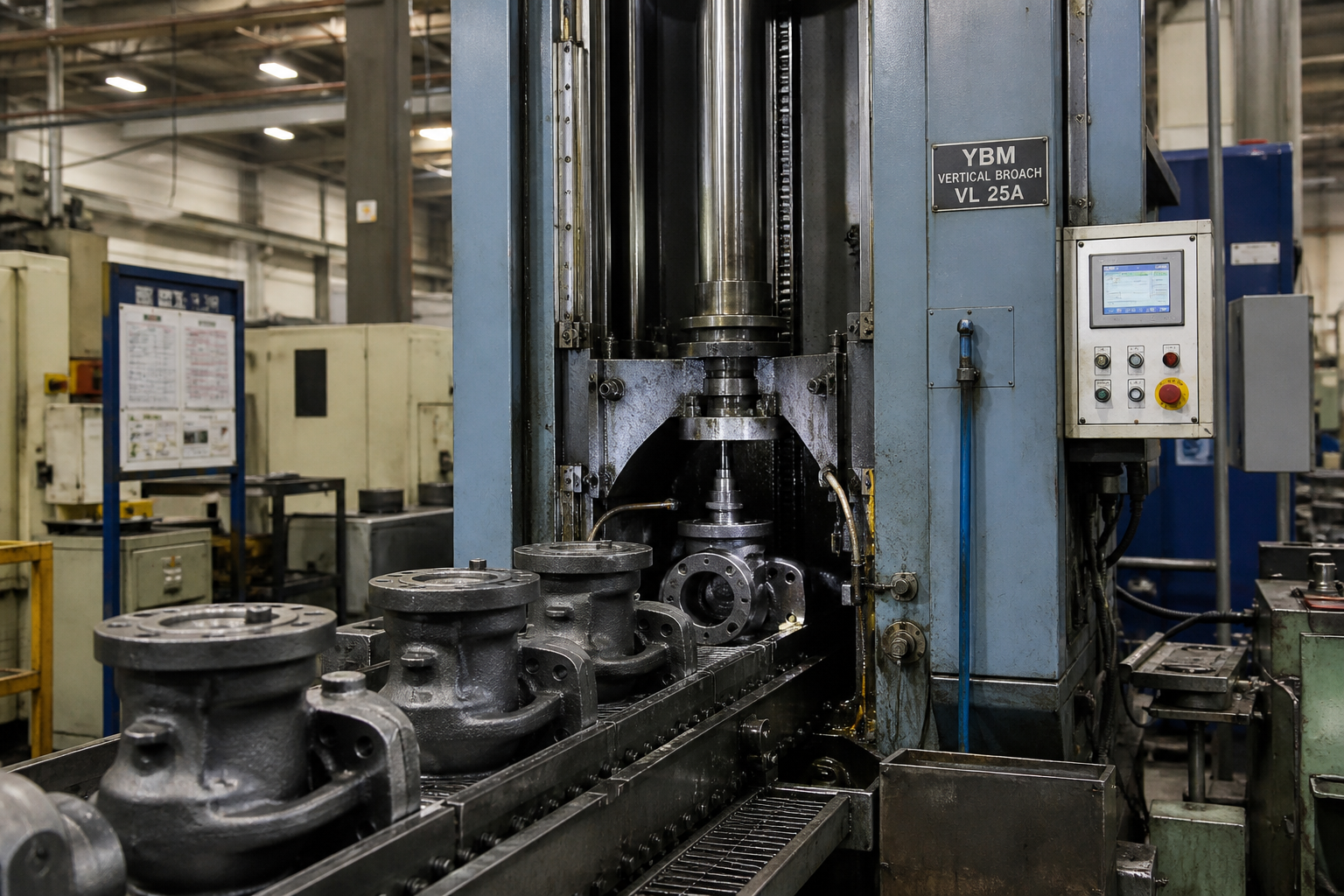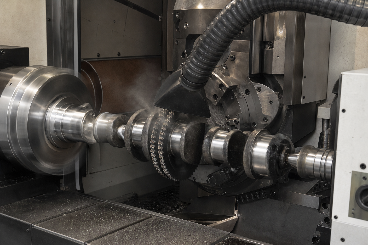
Barrels and tubes are a natural home for broaching. A barrel-shaped workpiece — a long cylinder with features formed along its bore — is exactly the geometry the process was built for: a long, straight stroke, a shaped tool that generates its profile in one pass, and repeatability that comes from the tool rather than from machine interpolation. The most famous member of this family is gun barrel rifling, a broaching-based process with over a century of industrial history. But the same platform also cuts straight grooves, annular recesses and internal forms in hydraulic cylinder components, tube fittings, bushings and general tubular parts.
This article covers barrel broaching as a workpiece case, in the same format as our cylinder block article. We start with what the process is and what makes tubular parts a distinct machining problem, then walk through rifling as pure manufacturing technology: the hook-cutter cutting process, how the helical motion is generated, and how cut rifling compares with button rifling and hammer forging. From there we cover the tooling challenges of slender parts and deep bores, the machine architecture the work demands, the non-firearm applications that share it, and how groove geometry is inspected.
What Is Barrel Broaching?
Barrel broaching is the application of broaching to cylindrical and tubular workpieces — parts whose machined features lie along the inside of a bore rather than on an exterior face. In its internal form, the process pulls or pushes a slender, toothed tool through the bore. Each successive tooth stands slightly taller than the one before it, so a single stroke takes the feature from entry to finished depth while the tool’s ground profile sets the groove’s cross-sectional shape. The fundamentals — tooth rise, chip load, cutting speed — are the same ones covered in our primer on what broaching is; what changes here is the workpiece.
Two feature families dominate. The first is the helical groove: a continuous channel that spirals along the bore at a defined lead. Gun barrel rifling is the best-known example — multiple grooves cut at a controlled twist — but helical internal grooves also appear in non-firearm parts where a helical path guides, mixes or distributes. The second is the straight or annular internal feature: keyways, lubrication grooves in bushings, snap-ring recesses and formed profiles in fittings and cylinder components. Both families share the same requirement — a shaped internal profile, generated accurately, deep inside a cylinder — and both are why the process earns its place on tubular parts.
The Barrel as a Machining Problem
Geometry That Works Against Conventional Tools
Tubular parts concentrate difficulty in three places. First, length-to-diameter ratio: a rifle barrel blank or a hydraulic cylinder tube can be many times longer than its bore, so any tool reaching the far end works at extreme overhang, where rigidity collapses and chatter begins. Second, inaccessibility: the surfaces that matter are inside the part, invisible to an external cutter and awkward to gauge. Third, slenderness and wall thickness: long cylinders deflect under cutting and clamping forces, and thin walls spring and ovalize — so the process has to manage the part’s shape, not just remove metal.
Materials and Blank Conditions
Gun barrel blanks are typically medium-carbon chromium-molybdenum alloy steels or martensitic stainless steels, supplied bored to a smooth, accurate pilot hole before rifling; the broach does not drill the bore, it cuts features into an already-finished hole. General tubular parts span a wider range: cold-drawn and honed hydraulic tubing, carbon and alloy steel bar stock, cast iron and bronze bushing materials, and non-ferrous fittings. The common thread is that the bore is pre-machined — drilled, bored, reamed or honed — and broaching arrives as the feature-forming step. The blank’s bore diameter, straightness and surface condition are first-order inputs to broach design, because the tool pilots in that bore.
How Rifling Is Broached: Hook Cutters and Progressive Passes
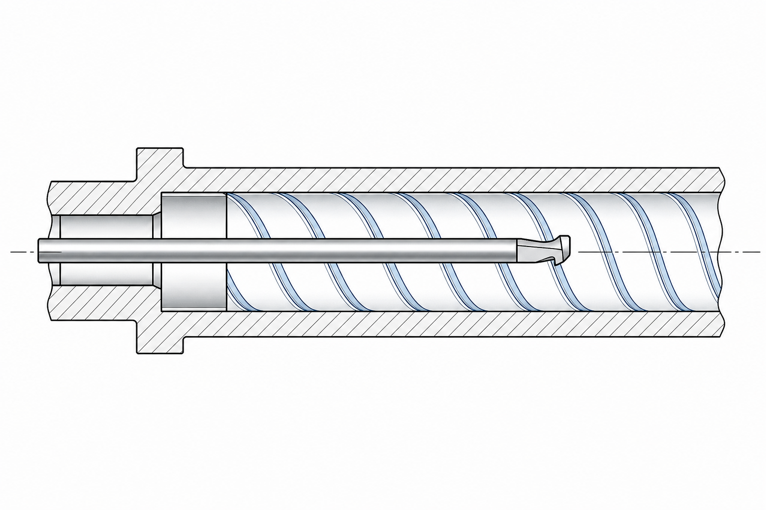
Rifling is a set of helical grooves cut into a bore, with the raised metal between them forming lands. In broached — or “cut” — rifling, the grooves are produced one at a time by a single-edge tool: a hook cutter, which cuts with a hooked edge drawn along the groove, or a scrape-style cutter with a different edge geometry. The tool is ground to the groove’s width and profile, mounted at the end of a long cutter bar, and drawn through the bore while the tool-and-part system rotates at a controlled rate, so the cutter traces the helix rather than a straight line.
Because the full groove depth is far too great for a single pass, the process is progressive. Each pass removes a thin slice of depth — small, controlled increments that keep cutting forces low and leave the bore’s stress state undisturbed — then the tool is retracted clear of the cut, reset deeper, and drawn again. A groove is finished after multiple passes, the cutter is indexed to the next groove position, and the cycle repeats until every groove in the set — commonly four, six or eight, per the barrel design — is complete. The grooves’ depths accumulate under the same tool, the same geometry and the same machine, which is where the process’s consistency comes from.
The helical motion itself is generated one of two ways, and the choice defines the machine. In one arrangement, the workpiece is held in a rotating fixture driven at a rate synchronized with the stroke, so the part turns while the cutter travels straight. In the other, the part stays still and the cutter bar is driven through a helical guide — a cam-type mechanism that converts the stroke’s linear motion into a precisely proportional rotation of the tool. Either way, the principle is the one we cover in our helical broaching guide: the ratio of stroke travel to rotation is fixed by the mechanism, so lead accuracy is designed into the machine rather than interpolated by it. The twist rate — one turn in a given number of inches or millimeters of travel — is set by that ratio and the gearing behind it.
Cut Rifling, Button Rifling and Hammer Forging Compared
Rifling is one of the few features in machining where three fundamentally different processes compete for the same work, and an engineer should understand all three on their manufacturing merits.
Cut rifling — the broaching family. Material is removed by an edged tool in multiple shallow passes. The defining characteristics: cutting forces are low, so the blank is left essentially free of induced residual stress; groove form and twist are set by tooling and machine kinematics, so changing twist rate is a setup change rather than a tooling reinvention; and the equipment is modest in cost relative to the alternatives. The trade is cycle time — multiple passes per groove — which is why cut rifling is the natural choice in custom, short-run and specialty barrel production, where flexibility and low distortion matter more than takt time.
Button rifling. A carbide button — a polished, groove-shaped die sized larger than the bore — is pushed or pulled through the blank in a single pass, displacing metal into the groove form rather than cutting it. The process is fast, the surface it leaves is smooth and work-hardened, and button tool life is long. Its engineering costs: it demands substantial force, the displaced material stores elastic stress that can release as bore distortion later (so stress-relief heat treatment typically follows), and finished geometry depends on how the material flows around the button — making blank consistency a process variable. Button setups suit mid-to-high volume production of a fixed groove design.
Hammer forging. The bore is formed over a mandrel that carries the negative of the complete rifling pattern, while concentric hammers forge the barrel material down onto it in a single high-speed operation. It is the highest-volume rifling process in existence and dominates military and high-volume sporting production; the forged bore surface is dense and consistently formed. The barrier is capital: hammer forging machines and calibrated mandrels pay only at very large volumes of an unchanging design, and per-design flexibility is the lowest of the three.
The comparison is strictly process economics. Cut rifling wins where variety, low stress and tool-driven accuracy are weighted; button wins on speed for a stable design; forging wins at maximum volume with maximum capital. Our interest is the first branch, and the machinery that serves it.
Tooling Challenges: Slender Cutters, Deep Bores and Chip Control
The slender tool. A rifling cutter bar or a long internal broach working at high length-to-diameter ratio has limited rigidity by nature. Under cutting load it deflects, and deflection in a rifling setup shows up directly as groove depth and position error. The countermeasures are classic: pilot the tool in the finished bore so it is guided rather than free; keep the cutter bar as short and as large in diameter as the bore allows; support it at both ends where the machine permits; and above all, keep the per-pass chip load small — the multi-pass strategy exists precisely to keep forces within what a slender tool and a thin-walled part can carry.
Chip evacuation. In a deep bore, chips are generated far from the nearest opening, and rifling chips are thin, stringy scrapings rather than the compact chips of roughing operations. Left in the bore they pack under the cutter, score the finished lands and smuggle depth error into the next pass. The process relies on directed coolant flow through the cutter bar or from the tail end of the bore to flush chips clear, cutter geometry ground to break the shaving, and a retract-and-clear return stroke. Bore cleanliness between passes is not housekeeping — it is a dimensional control.
Indexing and depth control. Because grooves are cut one at a time and indexed around the bore, the indexing mechanism’s accuracy decides groove-to-groove spacing uniformity, and the depth-setting mechanism’s resolution decides how finely the progressive passes are stepped. Both are specified and calibrated as part of the tooling package, not left to operator feel. The same discipline carries over to general tube broaching, where a multi-tooth broach’s tooth spacing, rise per tooth and guide pads do the same work in one pass.
Machine Requirements: The Long-Stroke Horizontal Platform
The workpiece dictates the architecture. Stroke must cover the barrel length plus tool approach and overrun, and rifle barrels run long — so the machine is long by design. Slender parts and slender tools both behave best horizontal, supported along their length instead of hanging, with chips and coolant able to drain out of the bore under gravity. The result is the long-stroke horizontal broaching machine, the platform we treat in our horizontal broaching machine guide: a rigid bed, a guided slide or pull mechanism, and workholding arranged on the machine’s axis.
Around that platform, barrel work adds specific equipment. Steady rests support the workpiece — and on some configurations the extended cutter bar as well — at intervals that keep deflection out of the cut. The helical capability appears either as a synchronized workpiece rotation drive or as an integrated helical guide, with twist rate set by changeable drive components. Indexing hardware positions each successive groove, and the depth-advance mechanism steps the tool between passes. Force requirements are moderate by broaching standards — the multi-pass strategy keeps loads low — but stroke length and guidance quality are non-negotiable. With the helical hardware disengaged, the same platform runs straight-pull tooling for the general tubular parts in the next section. It is the architecture behind our dedicated barrel broaching machine, and the same broaching machines family covers the straight-groove and external work that shares the floor with it.
Beyond Rifling: Tubes, Cylinder Components, Fittings and Bushings
The word “barrel” in a machine shop means more than one thing, and a barrel broaching machine is built for all of them. The non-firearm side of its workload is substantial, and it shares tooling logic, fixturing and platform with rifling work.
Hydraulic cylinder components. The precision bore of a cylinder tube belongs to honing — a settled division of labor, the same one we respect throughout this site’s workpiece cases. What broaching takes is the formed internal hardware around that bore: grooves and profiles in cylinder end caps and gland components, keyways and slots that locate or drive, and internal features in the heads and caps that close the tube — shaped internal profiles repeating at volume, in parts that are round and often tubular in their own right.
Tube fittings and adapters. Machined fittings in steel, stainless and brass carry internal recesses, retaining grooves and formed sealing seats, frequently at production quantities and always with the requirement that the form repeat identically part after part. A small internal broach generates such features in one pass, with no bore damage and no dependence on operator skill.
Bushings and sleeves. Plain bearings and guide sleeves in cast iron, bronze and steel are classic straight-groove work: lubrication distribution grooves — axial, circumferential or patterned — plus locating recesses and snap-ring grooves, cut into bores that are otherwise finished. The broach cuts the groove without disturbing the finished surface on either side of it, which is the property that keeps broaching in the bushing shop decade after decade.
Accuracy and Inspection: Groove Profile and Lead
Two geometric outputs define a broached barrel feature, and each has an inspection discipline. The first is groove cross-section — width, depth and form. Profile is inspected by casting the groove in a replicating compound and measuring the cast, probing it on a coordinate measuring machine, or checking it with form gages built to the groove’s nominal shape. Depth is the critical dimension in rifling work, because land height — the difference between groove floor and land surface — accumulates from pass to pass; it is verified on the finished part rather than assumed from the depth-setting dial.
The second is lead, or twist — how far the groove advances per turn. Lead error is a kinematics problem: it traces back to the helical guide or drive ratio, to synchronization error between stroke and rotation, and to any slip in the drivetrain. It is measured by tracking the groove’s angular position along known axial stations — on a dividing head with a probe or an optical twist-measuring setup — and comparing the actual advance against nominal. Groove-to-groove spacing uniformity, set by indexing, completes the picture. Across all three, the inspection reality of broaching matches its production reality: the geometry lives in the tooling and the machine’s kinematics, so measurement confirms rather than corrects — and drift points back to a specific, findable mechanism, whether cutter wear, guide condition or index positioning.
Related Broaching Cases on This Site
Barrel broaching is one workpiece case in a series. The nearest neighbor in method is our cylinder block broaching case — another long-established application where the value of the process is knowing which features it takes and which it leaves to boring and honing. The connecting rod case follows the same format, as do the transmission and brake-family cases, each asking the same questions: what repeats, what the part demands of the machine, and where the process genuinely wins.
Frequently Asked Questions
How is rifling broached?
With a single-edge hook or scrape cutter, one groove at a time, in multiple shallow passes. The cutter is ground to the groove’s width and profile, drawn through the pre-finished bore while the part or tool rotates at a fixed ratio to the stroke — the helical motion — then retracted, advanced deeper, and drawn again. When a groove reaches full depth, the tool indexes to the next groove position until the full set is cut. The shallow passes keep cutting force and induced stress low, which is the process’s defining advantage.
What is the difference between hook broaching and button rifling?
Hook broaching removes metal: a cutting edge shaves the groove out in progressive passes, keeping forces low and residual stress minimal, at the cost of more passes and slower cycle time. Button rifling displaces metal: an oversize carbide die is forced through the bore in one pass, forming the grooves by plastic flow — fast, with a smooth work-hardened surface, but it needs high driving force, leaves internal stress that typically requires relief heat treatment, and locks in one groove design. Cut rifling is favored for flexibility and low distortion; button for speed on a stable design.
What is a barrel broaching machine?
A long-stroke horizontal broaching machine configured for cylindrical work: stroke length sized to barrel and tube lengths, steady rests supporting slender workpieces and tool bars, workholding or tool drives arranged for helical motion (a synchronized rotation drive or a helical guide setting the twist rate), indexing hardware for groove-to-groove positioning, and a depth-advance mechanism for progressive passes. With the helical hardware disengaged, the same platform cuts straight internal grooves in general tubular parts — one machine, two workloads.
Can hydraulic cylinder tubes and other tubular parts be broached?
Yes — with the same division of labor this site applies everywhere. The precision bore of a hydraulic cylinder is honed, not broached; broaching takes the formed internal features around it, such as grooves and profiles in cylinder end caps and glands, keyways and locating slots, and recesses in fittings. Bushings and sleeves in cast iron, bronze and steel are likewise standard work: lubrication grooves, retaining recesses and snap-ring grooves cut into an already-finished bore without disturbing the surfaces on either side.
If your workpiece is a barrel, tube or cylindrical component with internal features that must repeat — rifling, helical grooves, keyways, lubrication or retaining grooves — that is the work this platform is engineered for. Send the part drawing, material specification and annual volumes, and our engineering team will return a machine, tooling and fixturing configuration with stroke and cycle time worked out against your part. Start on the barrel broaching machine page, or contact us directly with your workpiece details.