
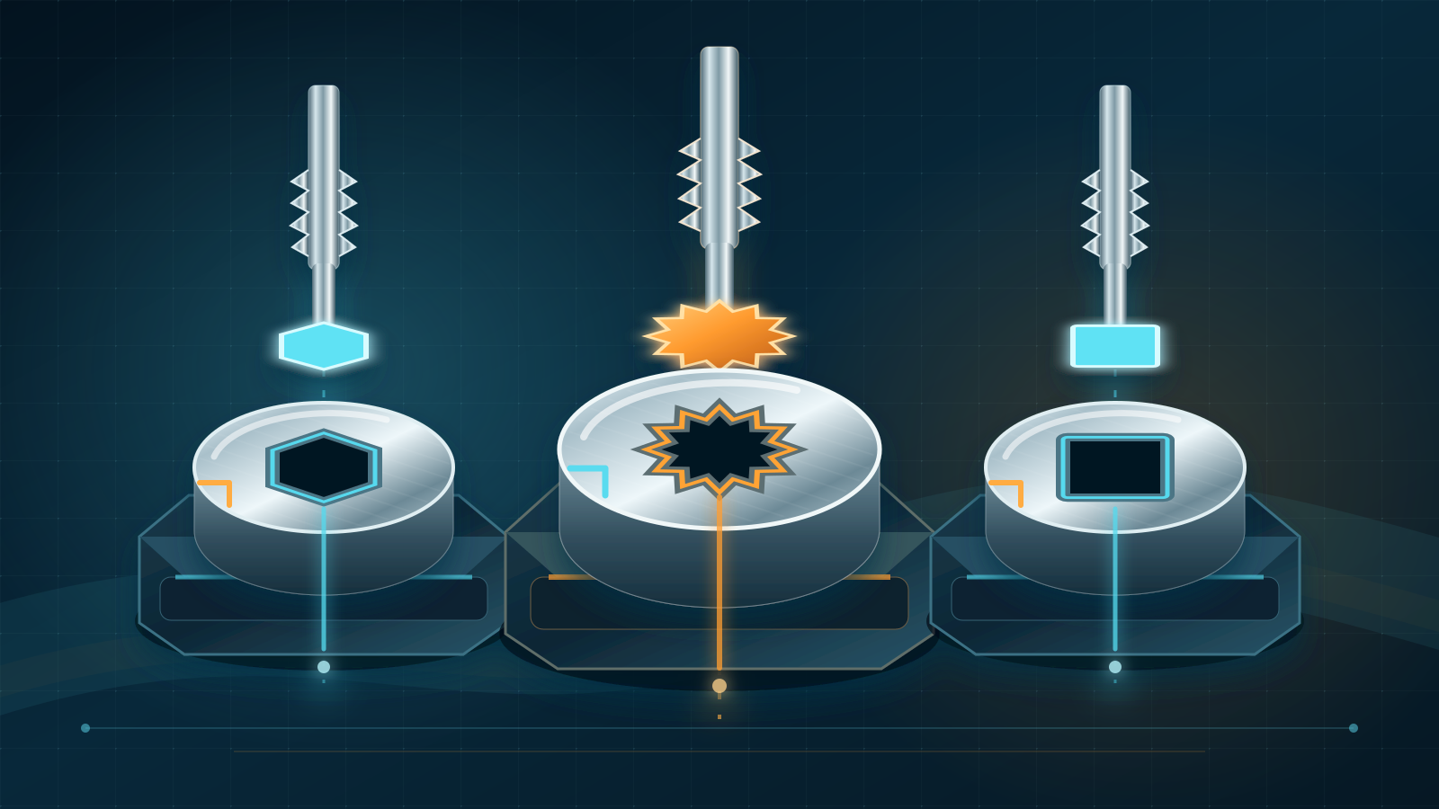
Conceptual illustration of polygonal profiles and candidate broaching routes. It is not a dimensional drawing, a customer part or a photograph of BroachingMach equipment.
Hex broaching uses a shaped cutting tool to generate a six-sided internal socket or external male profile. The correct method is not determined by the word “hex” alone. It depends on whether the feature is internal or external, through or blind, how deep it is, what corner condition the drawing allows, how it is oriented to other datums, and whether a progressive linear tool, rotary broach or single-point process can reach the cut.
Double-hex and square profiles add different geometry and inspection questions. A double hex is commonly described as a 12-point form, while a square has four flats and larger corner-to-corner material removal for a given across-flat size. Neither should be treated as a minor size change to a standard hex tool.
This guide connects profile definition, method selection, pre-hole and relief design, machine and fixture requirements, inspection and sample validation. It does not prescribe universal feeds, pilot-hole formulas, force or tolerance.
Define the Profile Before Choosing a Broach
Start with the controlled drawing rather than a tool catalog. At minimum, identify:
- Internal female socket or external male profile
- Hex, double-hex/12-point, square or a custom polygon
- Across-flat and corner or envelope limits
- Profile depth or axial length
- Through feature, blind feature or external end form
- Permitted corner radius, drill witness and lead-in
- Angular orientation to a hole, flat, thread, keyway or other datum
- Material specification, heat-treatment condition and coating sequence
- Functional mating part and required fit
- Inspection method and acceptance standard
The terms “hex,” “12-point” and “square” describe nominal shapes, not a complete tolerancing scheme. A supplier needs the drawing or validated digital definition, including any governing standard and revision. If the part must accept a driver, the functional interface matters more than a visually sharp polygon.
Internal Hex and External Hex Are Different Operations
An internal hex is a female profile inside a prepared opening. A linear broach carries cutting teeth on its outside and travels through the starting hole. A rotary internal broach presents the polygonal face to the workpiece and advances axially while its holder creates the characteristic progressive cutting action.
An external hex is a male profile on the outside of a shaft or boss. Candidate routes include external rotary broaching, surface broaching, pot-style tooling, milling or polygon turning. The cutting tool must clear surrounding shoulders, and the fixture must prevent the part from rotating or bending under load.
Do not put internal and external hexes into one undifferentiated tooling request. Their cutters, holders, blank preparation, support, chip paths and gages are different even when the nominal across-flat dimension is the same.
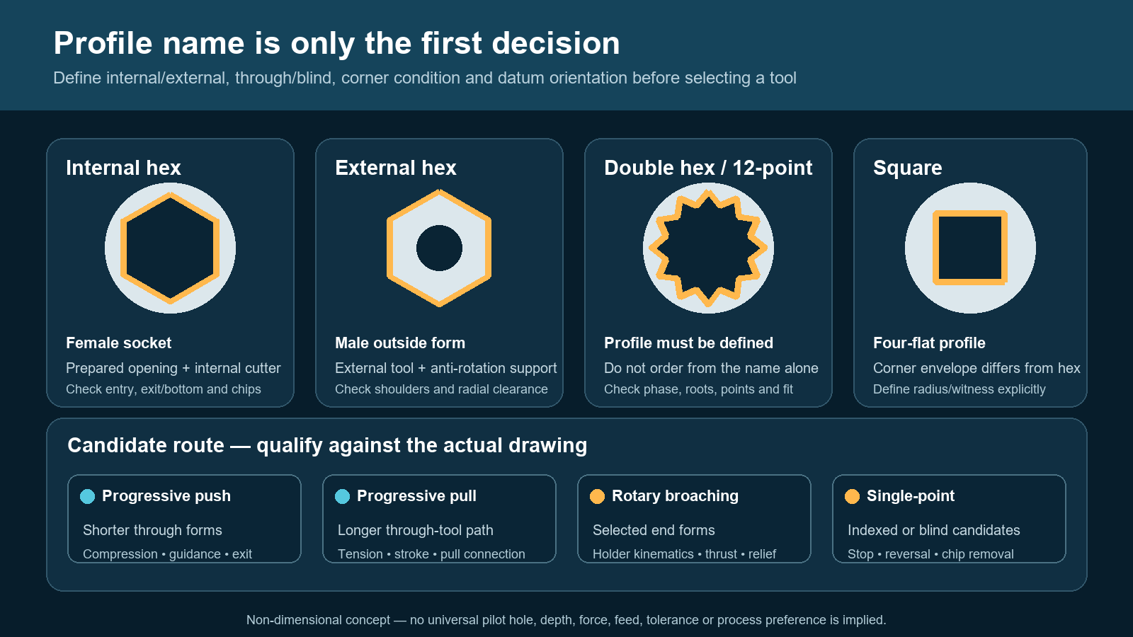
Non-dimensional method map. The drawing, access, depth, corner condition and production plan determine the route; the diagram does not prescribe a tool or machine.
What Is Double-Hex Broaching?
A double hex is commonly called a 12-point form because the finished profile presents twelve points. It is often used where a mating driver or socket benefits from more possible engagement positions. However, “double hex” is not enough to release a tool order.
The drawing must define the actual profile, across-flat or functional size, point and root condition, angular phase, fit and gaging requirement. Do not assume every 12-point profile is simply two ideal hexagons overlaid at a fixed angle. Manufacturing standards, product standards and proprietary forms may control different details.
Pilot-hole size is especially important. A larger starting hole reduces the stock removed at the center of the flats or roots, but it also leaves a visible radius or witness. That condition may be functional and acceptable—or it may violate the print. The toolmaker and customer should agree on the material envelope before deciding whether rotary, progressive linear or another method is viable.
Where Square Broaching Fits
Square broaching belongs in the same selection discussion because it uses many of the same candidate routes, but it is not interchangeable with hex broaching. For the same across-flat size, a square reaches farther toward its four corners. Starting-hole diameter, corner condition and cutting load therefore change.
Commercial push-broach families distinguish between square results that retain a controlled radius or witness and “full square” approaches intended to develop more of the flat. Those names are supplier-specific. Specify the finished geometry instead of relying on the catalog label.
Compare the Four Main Process Routes
Progressive push broaching
A push broach is driven through the workpiece in compression. Its teeth progressively enlarge a prepared opening into the target shape. It is commonly considered for relatively short internal through features and may run in an arbor press, hydraulic press or dedicated machine.
Because the tool is compressed, straightness, unsupported length, guidance and buckling risk matter. The workpiece must sit squarely over a clear exit path, and the support must carry force without distorting a thin wall or face. A “one-pass” catalog description still means multiple progressively sized teeth cut during one machine stroke; it does not mean the part requires no drilling, chamfering, deburring or inspection.
Progressive pull broaching
A pull broach is gripped and drawn through the workpiece in tension. A longer tool can distribute stock removal over more teeth and can be attractive for repeat production of through internal profiles. The system needs a suitable pull head or connection, adequate stroke, tool guidance, retrieval and safe handling.
Pull broaching is not automatically the best route for every deep feature. The broach must enter, connect and exit; the machine must accommodate total tool and workpiece length; and force must be evaluated over the complete tooth engagement. See the push-versus-pull broaching guide for the structural distinction.
Rotary broaching
Rotary broaching—also called wobble broaching—uses an angled holder or equivalent kinematic arrangement so the polygonal cutting face engages progressively rather than loading the full perimeter equally at once. Depending on the machine and holder, the workpiece or holder rotates while the tool advances.
This route is prominent in current hex and double-hex search results because it can integrate polygon generation into suitable lathes, mills, screw machines and transfer equipment. It can address selected internal and external end features. Suitability still depends on profile size, depth, material, alignment, available thrust, holder/tool geometry, relief and chip evacuation.
Published supplier angles, speeds, feeds and pilot-hole formulas apply to their systems and tested conditions. They should not be copied into an unrelated application without review and trials.
Single-point slotting or shaping
A single-point tool can generate a polygon by cutting one wall, corner or indexed segment at a time. This includes dedicated keyway/slotting equipment and CNC reciprocating-tool approaches. It may be useful when a long progressive broach cannot pass through the feature, when the part is blind, or when lower volume does not justify a dedicated form tool.
The tradeoff is a larger programming, indexing and cycle burden. Tool deflection, stroke reversal, bottom clearance, chip removal and angular accumulation must be controlled. A blind-profile strategy should be treated as its own process plan, not as a through-broach operation with the exit removed. The blind keyway guide explains many of the same stop, relief and chip-control issues.
Through Hole or Blind Feature?
A through internal profile gives a progressive push or pull broach somewhere to enter and exit. It also provides a potential chip path. Confirm that the finished profile and all tool sections can clear the part and fixture throughout the stroke.
A blind internal profile ends inside the workpiece. Important questions include:
- Where does the cutting tool stop and reverse?
- Is a bottom relief or overtravel cavity permitted?
- Where do chips and trapped cutting fluid go?
- Can the tool withdraw without rubbing, wedging or damaging the new profile?
- Must the polygon reach a flat bottom, or can a transition remain?
- Can a single-point or rotary route reach the required depth and corner condition?
Do not promise a blind hex merely because a rotary broach or reciprocating tool can enter the bore. The usable depth, bottom condition and evacuation route must be validated on the actual geometry.
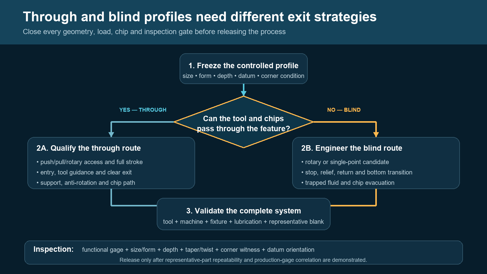
Engineering workflow from feature access to method, relief, chips and inspection. All dimensions and acceptance limits must come from the controlled drawing and trial plan.
Plan the Starting Hole, Lead-In and Runout Together
The starting hole removes central material before the form tool cuts the flats and corners. Its diameter influences remaining stock, cutting force, chip size and the radius or witness visible in the finished profile. There is no safe universal percentage because the correct choice depends on geometry, standard, material, process route and functional contact.
The process plan should define:
- Starting-hole diameter, roundness, straightness and position
- Drilled, bored, reamed, cast or formed pre-hole condition
- Entry chamfer or lead-in that is permitted by the drawing
- Required broached depth and allowed transition
- Through exit, undercut, bottom relief or chip pocket
- Deburring and edge-break operations
- Air, coolant and chip escape route
Trapped fluid in a blind hole can add hydraulic resistance and disrupt tool motion. A relief path may be required, but its design must not weaken the tool or violate the part. Chip space must be evaluated over the entire cut, not just at initial contact.
Tool, Machine and Fixture Must Be Sized as a System
Polygonal broaching is not only a cutter decision. The toolmaker and machine supplier need to review the complete load path:
drive → ram or pull head → holder/broach → workpiece → fixture → machine structure
Estimate force from the actual material condition, stock distribution, number of simultaneously engaged edges, tooth rise or cutting sequence, cut length, friction and tool condition. Then check machine capacity, stroke, daylight, connection, stiffness, alignment and return motion with an appropriate engineering margin. The broaching tonnage guide describes the required inputs without substituting a nameplate value for process validation.
The fixture should locate from drawing datums, support the cutting load close to the feature and leave clearance for the tool and chips. It must also control angular orientation when the polygon is clocked to another feature. Thin sections may need distributed support; asymmetric external cuts may need anti-rotation control.
Lubrication and coolant delivery must match the tool, material, chip route and machine. Use the broaching cutting-fluid guide as a screening framework, then validate the actual fluid and delivery method during trials.

RäumenMach hydraulic double-cylinder pull-down internal broaching machine. This is a real related linear internal-broaching platform, not a dedicated hex machine and not evidence of a specific hex, double-hex or square customer project.
BroachingMach publishes Innenräummaschine, broach tool and tooling-design resources. A supplier still needs to qualify the exact polygonal application before selecting a machine or tool.
Build Inspection Around Function and Datums
A go/no-go gage can support fast production decisions, but it does not explain every source of variation. Build the plan from the controlled characteristic.
For an internal hex, consider:
- Functional plug or mating-driver gage
- Across-flat size and profile at more than one depth
- Angular orientation to the datum system
- Taper, bell-mouth, twist or spiraling
- Corner radius, drill witness and entry condition
- Broached depth, bottom transition and burrs
For an external hex, a ring or functional female gage may be appropriate, with dimensional or CMM checks for across flats, straightness, orientation and runout. For a double hex, inspection must resolve all twelve points or flanks, their angular phase, root/point condition and functional engagement. For a square, include across-flat size, diagonal/corner condition, depth and clocking.
CMM, optical profile measurement or sectioning may be needed during development. Correlate any production gage to the drawing and measurement system. A gage that accepts the mating function does not automatically prove every form and location requirement.
Validate Representative Parts Before Release
Use material and geometry that represent production, including the expected hardness range, pre-hole variation and prior operations. A controlled trial should record:
- Tool and holder identification, setup and alignment
- Blank, material condition and pre-hole measurements
- Machine force or thrust trace where available
- Motion, lubrication and chip behavior
- First-off profile, depth, orientation and surface condition
- Tool-edge condition after defined checkpoints
- Measurement-system results and gage correlation
- Reaction plan for drift, overload, wear or chip packing
Do not release the process from one acceptable part. Confirm repeatability across representative blanks, tool condition and setup cycles. Define when the tool is inspected or resharpened using measured part, process and tool signals; the broach resharpening guide provides that framework.
RFQ Checklist for Hex, Double-Hex or Square Broaching
Send the supplier:
- Controlled drawing, model and applicable standard/revision
- Internal/external designation and exact profile definition
- Through/blind condition, cut length and access envelope
- Material, heat treatment, hardness range and coating sequence
- Pre-hole and adjacent-feature condition
- Corner radius, drill witness, lead-in and relief allowances
- Datum, concentricity and angular-orientation requirements
- Annual volume, batch size and desired automation level
- Existing machine, holder and available stroke/capacity, if applicable
- Coolant and chip-handling constraints
- Inspection method, gage concept and acceptance plan
- Representative blanks or parts for trials
For contract production, use the production broaching discussion as a starting point, but require written application review and sample acceptance before assuming capability.
Häufig gestellte Fragen
Is double hex the same as 12-point?
The terms are commonly used together, but the drawing must define the actual profile, fit, standard, size, corner/root condition and inspection method. Do not order from the name alone.
Can a hex broach make a blind hole?
Some rotary or single-point approaches can machine selected blind profiles. Suitability depends on depth, bottom relief, chip and fluid escape, return motion, corner condition and tool access. A conventional progressive through broach needs a clear travel path.
Should I use push or pull broaching for an internal hex?
Push broaching is commonly considered for shorter through features and compact tools; pull broaching can distribute cutting over a longer tool under tension. The choice requires checks of geometry, stroke, force, tool stability, volume, fixture and machine arrangement.
Does a larger pilot hole always make broaching better?
No. It can reduce remaining stock and force, but it also changes the radius or witness left in the finished profile and may reduce functional contact. The permitted material envelope must come from the drawing and mating requirement.
How should a broached hex be inspected?
Use a drawing-based plan combining functional gaging where appropriate with dimensional checks for size, form, depth, corner condition, taper and orientation. Validate the production gage against a capable measurement method during process development.


