
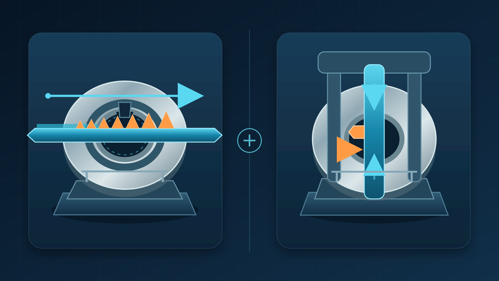
Conceptual illustration of two internal-keyway methods. It is not a dimensional process drawing or a photograph of a BroachingMach product.
When choosing broaching vs keyseating for an internal keyway, start with the feature—not with a claim that one method is always faster, cheaper, or more accurate. A progressive broach sends a multi-tooth tool through the bore; a keyseater generates the slot with repeated strokes of a single-point cutter. This difference affects access, guidance, chips, tooling, changeover and inspection.
As a practical starting point, progressive broaching is often a strong candidate for repeatable through keyways when the part family supports a dedicated tool and controlled setup. Keyseating is often a strong candidate when stroke control, feature flexibility, or blind-end access matters. Neither statement is a universal selection rule. The correct choice comes from the drawing, material condition, quantity and complete tool-machine-fixture-inspection system.
This article provides that selection framework. For a broader introduction to the broaching process itself, begin with Keyway Broaching: The Complete Guide.
Broaching and Keyseating Remove Material Differently
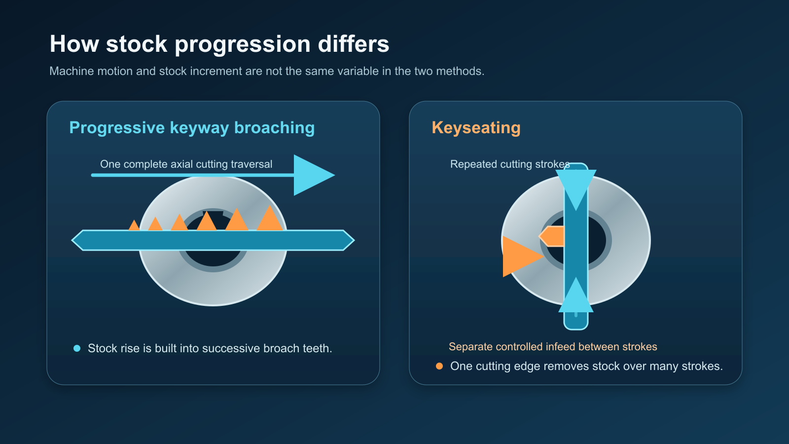
Progressive broaching distributes stock removal along successive teeth moving through the feature. Keyseating generates the keyway incrementally with repeated controlled strokes.
Progressive keyway broaching
A typical keyway broach has teeth that rise progressively along the tool. It is pushed or pulled through a guided bore, and one purpose-designed tool can include roughing, sizing and finishing action.
This process naturally connects tool length, keyway geometry, workpiece length and machine stroke. The workpiece and tooling stack must fit the machine envelope, the tool must remain guided through the cut, and it needs a safe exit and handling path after leaving the part.
Keyseating
A keyseater moves a cutter or cutter bar through a controlled reciprocating stroke. The edge removes material incrementally until the keyway reaches its required depth or form.
This incremental action may adapt to a range of lengths or depths without requiring a different progressive rise for every feature. Cutter-bar stiffness, bore access, stroke, guidance, workholding and chip space still limit the setup.
The terms describe cutting motions, not guaranteed results. A well-designed and validated system using either method can make functional internal keyways. A poorly matched tool, machine or fixture can produce an unstable process regardless of the method name.
Selection Gate 1: Through, Blind and Physical Access
The first question is whether the cutting tool can travel beyond the functional keyway.
Through internal keyways
A through bore with an open keyway path is the natural geometry for a conventional progressive broach. The tool can enter under guidance, complete the cut and exit from the opposite side. Chips can move out with the tool rather than collect against a closed shoulder.
Keyseating can also produce through keyways. Consider it when the part is awkward for the available broaching setup, geometry changes frequently, or existing keyseating capacity fits the route. An open feature removes one broaching constraint but does not decide the process.
Blind internal keyways
A blind keyway stops inside the bore. This prevents a conventional through broach from completing its normal exit path. Keyseating, slotting or a controlled single-point broaching method may be better candidates because their stroke can be stopped and reversed, provided the cutter can clear safely and chips have somewhere to go.
Blind access is not solved merely by choosing a reciprocating machine. The drawing needs a workable end condition; the edge must stop, clear and return without encountering packed chips. See Blind Keyway Broaching: Methods, Relief Design and CNC Setup for relief and blind-end details.
Access is more than “through or blind”
Review the full tool path:
- Is there room for the tool or cutter bar on the entry side?
- Can it extend beyond the far face, or do surrounding features block guidance or exit?
- Can the finished tool be removed without striking the part or fixture?
- Does the combined part, tool and holder fit the machine daylight and stroke?
A keyway can be open on the drawing and still be difficult to broach if the surrounding part prevents tool entry, support or exit.
Selection Gate 2: Keyway Length and Geometry
The keyway width and depth are only part of the definition. Process selection also depends on usable length, end condition, bore size, corner form, angular relationship and the distance from the machine or fixture support to the cutting zone.
Length and tool behavior
With progressive broaching, engagement, tool rise and tooth sequence are designed together. Keyway length can change load, chip accommodation and tool travel, so nominal width alone cannot select the tool.
With keyseating, longer reach or a smaller cutter bar can increase deflection risk. Stroke capacity alone does not prove that the unsupported length, guides and workholding can hold the geometry.
Profile and end form
A drawing may specify a root form, taper, multiple keyways or an angular datum. Confirm that the tool can generate the geometry and that inspection can distinguish tool form from process error.
Do not assume that catalog labels are interchangeable. A nominally matching keyway broach still has to be checked for bore guidance, length, material, tooth design, machine interface and required profile. Nonstandard features may require an application-specific broach tooling design review.
Part envelope and handling
A compact hub, thin ring and large gear blank can share a nominal keyway but need different fixtures. Compare location, support, loading and distortion risk—not only whether the cutter reaches the bore.
Selection Gate 3: Volume, Mix and Changeover
“Broaching for volume, keyseating for low quantity” is a useful hypothesis, not a decision rule.
A dedicated progressive broach can consolidate cutting into one pass once the tool, fixture and cycle are stable. Its business case still includes manufacture, maintenance, storage, regrinding and design-change risk.
Keyseating uses multiple strokes, but an adaptable cutter and setup may reduce variant-specific tooling. Whether flexibility outweighs cutting time depends on the real mix and machine utilization.
Evaluate these production questions:
- Annual demand, batch size and demand uncertainty.
- Number of keyway widths, depths, lengths and bore sizes in the family.
- Expected drawing revisions and product life.
- Changeover frequency and first-piece validation effort.
- Tool lead time, spare-tool policy and reconditioning route.
- Available machine hours and whether another operation becomes the bottleneck.
- Loading, cleaning, deburring and inspection time outside the cutting stroke.
Avoid choosing from a generic break-even quantity. Two shops making the same part can reach different decisions because they have different machines, labor content, tool inventories and production schedules.
Compare the Complete Process System
The cutting motion is only one element. A reliable comparison covers the tool, machine, fixture, lubrication and chip path, inspection plan and operating controls as a connected system.
Tool and machine
For progressive broaching, review the tool, guidance, push/pull interface, travel, support and capture. Nameplate tonnage does not prove tool life or keyway quality. Broaching machine tonnage inputs can support review but do not replace tool-specific load validation.
For keyseating, review cutter geometry, bar stiffness, feed, guides, usable stroke and end clearance. Confirm how depth is established and wear is detected; stroke specification alone cannot prove capability.
Fixture and datum control
Both processes need a fixture that resists load, locates the bore and angular datum, provides tool clearance, and lets chips and fluid leave.
For multiple keyways or an angular relationship, indexing becomes part of capability. Fast cutting adds little if loading or datum transfer creates variation.
Chips and lubrication
Progressive broach teeth carry chips along the tool, so tooth space, engagement and fluid delivery must prevent welding or packing.
Keyseating needs a deliberate route for chips to fall, flush or be removed, especially in a blind or vertical bore. Recutting chips can affect either method.
Fluid selection follows the material, tool and machine. The broaching cutting-fluid guide explains lubricity, viscosity, delivery and filtration; the fluid still must reach the edge and carry chips to effective filtration.
Inspeção
Define the acceptance method before tooling is released. Depending on the drawing and function, inspection may need to verify:
- Width, radial depth and usable keyway length.
- Straightness and taper along the bore.
- Angular position relative to the specified datum.
- Root form, end relief or runout geometry.
- Burrs, surface condition and damage at entry or exit.
- Bore condition after cutting and clamping.
Select gauges and measurement access that suit the part. A functional check may not show which variable moved, so first-off measurements should separate width, depth, angle and straightness.
Broaching vs Keyseating Selection Matrix
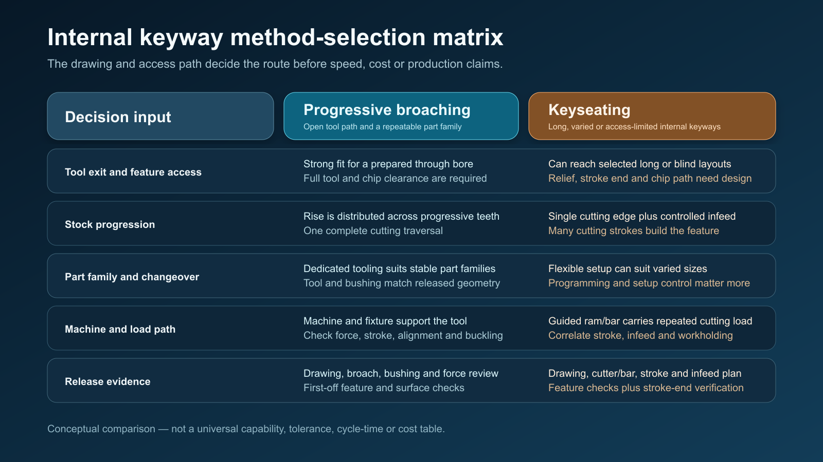
Use the matrix as a screening tool. Final selection requires the actual drawing, material, machine, fixture and inspection plan.
| Decision factor | Progressive broaching tends to fit when | Keyseating tends to fit when | Validation question |
|---|---|---|---|
| Tool path | The keyway has a clear through path | A controlled stop and return are needed | Where do the tool and chips go at both ends? |
| Feature family | Geometry is stable enough to support dedicated tooling | Width, depth or length changes are frequent | How many variants and changeovers are real? |
| Production route | A purpose-designed pass integrates well with loading and inspection | Incremental generation fits available capacity or flexible routing | What is the total cycle, not only cutting time? |
| Part envelope | The part and complete broach stack fit stroke and daylight | The part can be supported around a reciprocating cutter path | What interferes with entry, support or exit? |
| Tooling strategy | Tool lead time, storage and reconditioning are acceptable | A cutter-based system reduces variant-specific commitment | How will wear, spares and replacement be managed? |
| Workholding | The fixture can resist the progressive cutting load and guide the tool | The fixture can resist repeated strokes and preserve alignment | Which datum controls keyway position? |
| Chips | Tooth space and an open path can carry chips out | Repeated strokes have a deliberate evacuation route | Can chips leave without recutting or packing? |
| Inspeção | Stable dedicated tooling supports the required control plan | Adjustable generation and setup can be measured and corrected | Which measurement detects drift soonest? |
If the evidence is split, do not force a paper decision. A representative cutting trial can compare actual load, chip behavior, setup time, measurements and tool condition.
Compare Cost Without Inventing a Universal Break-Even Point
Compare the cost of a capable route over the expected program, not one tool price or cutting stroke.
Build both estimates from the same categories:
- Tool engineering, manufacture and initial prove-out.
- Machine and fixture preparation, including guidance and guarding.
- Changeover, alignment and first-piece approval.
- Cutting, loading, unloading, cleaning and deburring time.
- Inspection frequency and measurement labor.
- Tool wear, sharpening or insert/cutter replacement, and spare coverage.
- Coolant, filtration and chip handling.
- Expected nonconformance, troubleshooting and downtime exposure.
- Design-change risk over the forecast production life.
Use ranges for unknown demand, tool life or cycle performance. Any input that could reverse the choice becomes a trial or review requirement, not a guessed ROI assumption.
A Practical Validation Workflow
- Freeze the functional definition: bore, keyway width and depth, usable length, end form, angular datum, material condition and acceptance method.
- Map the physical tool path, including entry, guidance, cutting travel, chip route, exit or reversal, and tool removal.
- Screen progressive broaching and keyseating against machine stroke, clearance, support and handling.
- Develop a tooling and fixture concept for each feasible route.
- Estimate the complete production cycle and lifecycle cost using the same assumptions.
- Identify evidence gaps such as cutter deflection, broach load, chip packing, tool life or measurement access.
- Run a representative trial when those gaps materially affect the choice.
- Inspect the feature and tool, record load and chip behavior, and change one process variable at a time.
- Release the selected route with defined setup checks, wear limits, inspection frequency and reaction plan.
If neither method is a strong fit, screen EDM, slotting/shaping, CNC single-point broaching, accessible milling or a design change using the same drawing-led review.
RFQ Checklist for an Internal Keyway Review
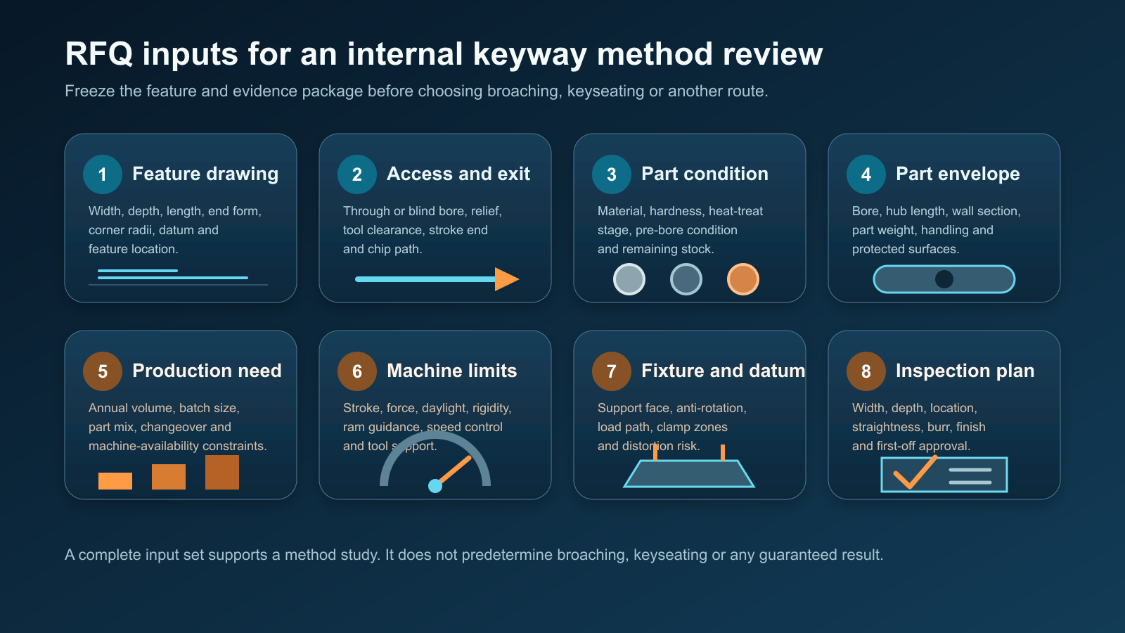
A useful RFQ connects feature geometry to the planned production system. Do not omit blind-end or access details from the drawing package.
Provide the following information when requesting a method or tooling review:
- Finished-part drawing and 3D model, with revision level.
- Bore diameter and length, keyway width, radial depth and usable length.
- Through or blind condition, including relief, shoulder and exit geometry.
- Root form, corner requirements and allowable runout at each end.
- Material grade, hardness and heat-treatment condition during cutting.
- Required tolerances, surface condition and angular datum relationship.
- Part mass, overall envelope and areas available for clamping.
- Annual quantity, batch size, product mix and expected design life.
- Available machine type, stroke, daylight, force data and tool interface.
- Existing fixtures, cutters, broaches, fluids and inspection equipment.
- Target production constraints and any current defect or tool-failure evidence.
Ask for an integrated process, tool, machine-interface, fixture, chip/lubrication and inspection recommendation. A tool quotation alone cannot confirm route capability.
Frequently Asked Questions
Is keyseating the same as broaching?
No. In the comparison used here, progressive broaching moves a multi-tooth tool through the feature so successive teeth remove stock. Keyseating generates the slot incrementally with a reciprocating cutter. Both can produce internal keyways, but they impose different tool-path, guidance, chip and setup requirements.
Is broaching always faster than keyseating?
No. A broach may consolidate cutting into one pass while keyseating uses repeated strokes, but total time also includes loading, changeover, cleaning, inspection and tool service.
Is keyseating always better for a blind keyway?
It is often a stronger candidate because the stroke can be controlled and reversed, but suitability depends on cutter clearance, bottom geometry, chips, guidance and machine capability. A blind feature still needs an engineered end and evacuation strategy.
Which method is more accurate?
Accuracy cannot be assigned from the process name. Tool condition, guidance, bar stiffness, fixture repeatability, machine motion and inspection all affect the result.
What is the difference between a keyway and a keyseat?
Terminology varies across industries. Commonly, “keyseat” refers to the slot in a shaft and “keyway” to the mating slot in a hub or bore, while some sources use “keyway” more broadly for either feature. This article uses “internal keyway” for the bore feature and “keyseating” for the reciprocating machining process.
Can one machine cover every internal-keyway job?
No. Bore size, length, access, part envelope, material, tool support, chips and inspection can move a job outside a machine's practical range. Confirm capability from the part and tooling concept.
Final Recommendation
Choose broaching vs keyseating by moving through three gates in order: physical access, feature geometry, and production model. Then validate the complete tool-machine-fixture-chip-inspection system.
Use progressive broaching as a candidate when the keyway has a clear through path, the geometry is stable, and dedicated tooling integrates well with the production route. Use keyseating as a candidate when controlled stroke or geometric flexibility has greater value. For blind, difficult-access or frequently changing work, do not commit until the tool clearance, chip route and inspection plan are proven.
Send the drawing and production requirements for an application review. The recommendation should be based on the real part and production system, not a universal claim about either process.


