目錄
- What Is Flat Broaching and How It Relates to Surface Broaching
- Flat Broach Tool Anatomy and Tooth Geometry
- Slab Broach vs. Straddle and Built-Up Surface Broaches
- Flat Broaching Process Parameters and Machine Selection
- Step-by-Step Flat Broaching Setup and Operation
- Common Flat Broaching Defects and Troubleshooting
- 常見問題
- Next Steps and Engineering Support
Flat broaching is a single-pass linear machining process that cuts an external flat surface by moving a stepped, multi-tooth tool across a clamped workpiece (or feeding the workpiece past a stationary tool). Because roughing, semi-finishing, and finishing teeth are ground into one tool body, the cut finishes to tight dimensional tolerance in one stroke without multi-axis CNC toolpaths.
Key takeaways
- Scope and audience: This guide is written for manufacturing engineers, process planners, and machinists evaluating flat broaching versus milling or grinding for medium-to-high-volume external planes.
- Built-in feed: Rise per tooth (RPT) and tooth pitch are fixed during tool manufacture, leaving cutting speed as the primary machine-side adjustment.
- Typical capability: Standard surface broaching holds
±0.002 in(±0.05 mm) tolerances and16–63 µinsurface finishes, tightening to±0.0005 in(±0.01 mm) in precision setups.- Economic threshold: Custom broach tooling can cost
US$15,000–30,000, making the process viable mainly for repetitive production runs rather than low-volume jobbing.
What Is Flat Broaching and How It Relates to Surface Broaching
Flat broaching is the simplest form of external surface broaching, dedicated to producing flat planes rather than internal holes, splines, or keyways. Unlike milling or shaping—where a cutter makes repeated passes and machine axes control feed—a flat broach carries its feed inside the stepped height of consecutive teeth, so the machined plane is the exact inverse of the tool profile, as documented in the Engineers Edge broaching process review.
In practice, surface broaching operates in one of two kinematic arrangements: either the workpiece stays clamped in a rigid fixture while the broach slide travels linearly across it, or the workpiece is carried past a stationary broach assembly. Because no starter hole is required—unlike internal broaching—external flat broaching eliminates pilot threading and broach-handling elevators, simplifying fixture loading and shortening cycle time.
This guide focuses strictly on linear external flat and parallel-plane broaching; rotary broaching on lathes and internal spline or keyway broaching require different tool mechanics and are outside the scope here. As noted in Sabancı University's broaching optimization thesis by Özkan Öztürk (2003), combining roughing, semi-finishing, and finishing in one linear stroke reduces setup time and yields high-quality surface finishes, but locking geometry into the tool means process engineers cannot alter depth of cut per tooth on the shop floor once the broach is ground.
Flat Broach Tool Anatomy and Tooth Geometry
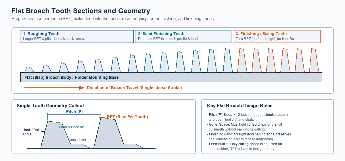
A flat broach functions like a sequence of single-point shaper tools arranged along a rigid bar or holder. In Cutting Tool Applications, Chapter 14: Broaches and Broaching (American Machinist, 2020), George Schneider explains that broach teeth are divided into three functional zones along the stroke, each governing chip load and final surface quality.
Functional Tooth Sections
- Roughing teeth: Positioned at the leading end of the broach, roughing teeth carry the largest rise per tooth (RPT) and wider tooth pitch to remove bulk stock rapidly without packing chips.
- Semi-finishing teeth: Following the roughing section, semi-finishing teeth step down the RPT so cutting forces taper off and surface waviness from heavy roughing cuts is leveled out.
- Finishing (sizing) teeth: At the trailing end, multiple finishing teeth are ground to identical height (zero RPT) so that minor edge wear on the first finishing tooth is cleaned up by subsequent sizing teeth.
Critical Geometric Features
- Tooth pitch and simultaneous engagement: Pitch is the axial distance from one cutting edge to the next. Schneider (2020) notes that pitch is calculated so that two or more teeth cut simultaneously, which prevents the tool from drifting or chattering across the workpiece face.
- Hook (rake) angle and friction: A positive hook or face angle sharpens cutting action and directs chip curl into the gullet; soft steels take larger hook angles than hard or brittle steels. In analytical force modeling, Öztürk (2003) notes that tool–workpiece friction angles typically fall around
30°to40°. - Tooth land and back-off clearance: On roughing and semi-finishing teeth, the entire land behind the cutting edge is relieved with a clearance angle to minimize rubbing. On finishing teeth, a narrow straight land is left immediately behind the edge so face resharpening does not shrink the finished dimension.
- Tooth gullet and chipbreakers: The gullet root radius curls chips tightly so they occupy minimal volume until exiting the cut. Staggered chipbreaker notches are ground into roughing and semi-finishing teeth on wide faces to split wide chips and prevent gullet jamming.
- Shear angle: Setting flat broach teeth at a slight diagonal shear angle eases entry and exit shock, reduces chatter, and pushes chips laterally away from corners when cutting intersecting planes.
Slab Broach vs. Straddle and Built-Up Surface Broaches
Choosing the right flat broach architecture depends on part geometry, production volume, and whether one or multiple planes must be held parallel. Solid tools suit compact, lower-force cuts, whereas modular holders dominate heavy industrial lines.
| Tool Type | Typical Geometry Cut | Construction Style | Best-Fit Production Scenario | Key Tradeoff |
|---|---|---|---|---|
| Slab broach | Single external flat plane | Solid HSS bar or segmented sections in sub-holder | General-purpose facing of bosses, pads, and blocks | Simplest setup; machines one face per pass |
| Straddle broach | Two parallel opposing flat surfaces | Twin slab broaches mounted in a rigid straddle holder | Parallel flats on forks, brackets, and bearing caps | Holds tighter parallelism than two separate passes; doubles cutting force |
| Built-up / insert broach | Wide planes, engine blocks, or stepped faces | Replaceable HSS sections or indexable carbide bits in a holder | High-volume automotive or heavy machinery lines | Lower replacement cost when one section wears; higher initial holder setup |
| Slot / contour broach | Parallel slots, grooves, or curved external profiles | Multi-row solid or modular blades | Multi-slot parts where milling requires multiple passes | Enclosed sides require side relief to prevent tooth rubbing |
As Engineers Edge details, a slab broach is the baseline general-purpose tool for flat surfaces, while straddle broaches mount two opposing slab broaches to machine parallel faces simultaneously in one stroke—holding closer parallelism than sequential setups. For large external work, Schneider (2020) observes that most production surface broaches use built-up construction with replaceable sections, inserts, or indexable bits bolted into a rigid holder on the machine slide, avoiding the expense of scrapping an entire solid bar when only a few teeth chip.
Tool Materials and Coatings
Tool material selection directly governs permissible cutting speed and edge life:
- High-speed steel (HSS) with TiN coating: Most flat broaches are ground from HSS or alloy steel; titanium nitride (TiN) coatings are widely applied to extend wear life between resharpening cycles, per Engineers Edge.
- Tungsten carbide: Solid carbide teeth crack easily on initial impact except when broaching cast iron, whereas indexable carbide inserts mounted in rigid horizontal surface holders enable the highest production speeds on cast-iron cylinder blocks and heads (Schneider, 2020).
Flat Broaching Process Parameters and Machine Selection
Unlike CNC milling, where feed rate and depth of cut are programmed in G-code, flat broaching fixes RPT in the tool and leaves only cutting speed, machine tonnage, and stroke length as machine-level variables. Matching the machine architecture to part width and cut length is essential before ordering tooling.
Surface Broaching Capability Benchmarks
| Parameter | Typical Industrial Range | High-Precision / Heavy-Duty Limit | Primary Source |
|---|---|---|---|
| Surface cut size | 0.075–10 in (1.9–254.0 mm) | 0.02–20 in (0.51–508.00 mm) | Wikipedia |
| Dimensional tolerance | ±0.002 in (±0.05 mm) | ±0.0005 in (±0.01 mm) | Wikipedia |
| Surface finish | 16–63 µin | 8–125 µin | Wikipedia |
| Optimal steel hardness | 16–24 HRC | Above 35 HRC accelerates dulling | Wikipedia |
| Standard cutting speed | 20–120 SFPM (5–30 s cycle) | 3–20 m/min in HSS alloy modeling | Wikipedia; Öztürk (2003) |
| Hydraulic horizontal surface | Up to 40 tons, 180 in stroke | Normal speed 100 FPM | Schneider (2020) |
| Electromechanical horizontal | >100 tons, up to 30 ft stroke | Over 300 FPM (carbide tooling) | Schneider (2020) |
Machine Configuration Choices
According to Schneider (2020), roughly 60 percent of existing broaching machines are vertical (split evenly between internal and surface/combination units), while 40 percent are horizontal, with horizontal surface machines representing about 10 percent of total installed units but a disproportionate share of high-volume output.
- Vertical surface broaching machines: Preferred when floor space is tight and moderate strokes suffice; however, very long vertical strokes can exceed shop ceiling heights and require floor pits for ergonomic loading.
- Horizontal surface broaching machines: Chosen for long strokes and heavy cast-iron facing. Electromechanical drives increasingly replace hydraulic cylinders on demanding lines because smooth ram motion improves surface finish and dimensional repeatability.
- Continuous chain-broaching machines: Built for maximum throughput on small-to-medium flat parts; workpieces ride on a continuous chain through a tunnel of stationary broaches, eliminating return-stroke idle time.
When selecting equipment for external planes or specialized part families, process engineers can review standard 拉削機 alongside dedicated flat broaches to align ram tonnage with total simultaneous tooth engagement.
Step-by-Step Flat Broaching Setup and Operation
Even a well-ground broach will chatter, drift, or produce out-of-flat parts if fixturing and fluid delivery are neglected. Follow this five-step shop-floor sequence when qualifying a flat broaching setup:
- Verify incoming stock and workpiece hardness: Measure pre-broach stock allowance against the total RPT built into the tool—excess stock overloads the first roughing teeth, while insufficient stock leaves uncleaned scale. Confirm steel hardness falls near the ideal machinability window rather than above
35 HRC, where rapid edge dulling begins. - Align and rigidly clamp the workpiece: Seat the part on hardened locating pads directly opposing the cutting thrust so the part cannot lift, tilt, or deflect under peak force. Keep clamping pressure uniform on thin-walled castings so the flat surface does not spring back out of flatness after unclamping.
- Mount the broach holder and check stroke clearance: Bolt the slab broach or segmented holder cleanly onto the machine slide with zero debris under the backing plate. Jog the ram through a dry stroke to verify smooth entry, full tooth disengagement at exit, and unobstructed chip clearance.
- Configure cutting fluid delivery: Aim high-flow nozzles directly at the tool–workpiece entry zone. As Engineers Edge notes, cutting fluid performs three essential roles: cooling both tool and workpiece, lubricating the cutting edges, and flushing chips out of the tooth gullets before they pack. Fortified petroleum oils dominate heavy cuts, while heavy-duty water-soluble fluids offer stronger cooling and cleaner operation.
- Run first-article inspection: Broach a test part at nominal speed, inspect flatness and surface roughness, and check the exit edge for small burrs that may require a secondary deburring pass or chamfer design adjustment.
Common Flat Broaching Defects and Troubleshooting
Because tooth geometry is fixed, shop-floor troubleshooting focuses on speed, clamping rigidity, fluid flow, and timely resharpening before edge wear compounds cutting forces.
| Observed Defect | Likely Root Cause | Corrective Action |
|---|---|---|
| Rough surface or torn finish | Built-up edge (BUE) on ductile steel, worn finishing teeth, or insufficient lubrication | Increase cutting speed within tool limits, upgrade fluid lubricity, or regrind finishing teeth |
| Out-of-flatness or taper | Workpiece deflection under clamping, debris under broach holder, or fewer than two teeth engaged | Re-seat holder backing, equalize fixture support under cut zone, or verify part length vs. pitch |
| Tooth chipping or breakage | Excess incoming stock overloading lead teeth, chip packing in gullets, or hard inclusions | Tighten pre-broach stock tolerance, increase coolant flush pressure, and check part hardness |
| Rapid edge dulling | Workpiece hardness above target range, dry cutting, or rubbing from inadequate clearance | Verify heat-treatment hardness before broaching and apply TiN-coated HSS or carbide inserts |
常見問題
How does flat broaching compare to face milling for flat surfaces?
Flat broaching finishes a plane in a single linear pass, achieving higher throughput and consistent surface finish without cutter-path scallops once production volume justifies tooling cost. Face milling remains far more economical for prototypes, low-volume batches, interrupted pockets, or parts requiring frequent engineering changes.
Why is cutting speed the only parameter adjusted on the machine?
Unlike milling or turning, where feed rate and depth of cut are programmed independently, a broach has its feed (RPT) and tooth spacing permanently ground into the tool. Operators can only adjust ram cutting speed—and select cutting fluid—while all chip-load changes require regrinding or redesigning the broach.
Can a flat broach be resharpened without changing part dimensions?
Yes, within limits. Resharpening is performed by grinding the tooth face (hook surface) rather than the top land. Because finishing teeth include a short straight land behind the cutting edge, several face-grinding cycles can restore sharpness before the finished height drops out of tolerance.
When is a straddle broach better than two passes with a slab broach?
When a part requires two opposite, parallel flat faces—such as connecting-rod caps, shifter forks, or bearing blocks—a straddle broach cuts both sides simultaneously in one stroke. This eliminates re-clamping errors between operations and holds tighter parallelism, provided machine tonnage can handle double the cutting force.
Next Steps and Engineering Support
Flat broaching delivers unmatched cycle-time consistency and surface quality for medium-to-high-volume external planes when tool geometry, machine rigidity, and chip flushing are engineered together. Before committing to custom tooling, confirm your part's cut length, stock allowance, material hardness, and required annual volume against machine tonnage capacity.
If you need help sizing a surface broaching machine, selecting slab versus built-up tooling, or reviewing part drawings for feasibility, contact our engineering team for process evaluation and tooling recommendations.
References
- Chapter 14: Broaches and Broaching | Cutting Tool Applications | American Machinist — George Schneider (2020); supports tooth nomenclature, pitch/simultaneous-tooth rules, built-up surface broach design, and vertical/horizontal surface machine capacities and speeds.
- Modeling of Broaching for Optimization Purposes — Özkan Öztürk, Sabancı University (2003); supports built-in tool parameter constraints, friction angle range, and broaching cutting speed test range.
- Broaches / Broaching Manufacturing Process Review — Engineers Edge; supports surface/slab/straddle broach definitions, cutting fluid functions, and HSS/TiN vs. carbide material behavior.
- Broaching (metalworking) – Wikipedia — Wikipedia; supports surface broach size ranges, dimensional tolerances, surface finish benchmarks, steel hardness limits, and tooling cost range.