

Conceptual illustration of a production team reviewing broach condition, part quality and machine-load trends. It is not a photograph of a BroachingMach customer site and does not imply a specific wear limit.
Ask how long a broach lasts and the honest answer depends on what “lasts” means and on the complete cutting system. A tool may still cut while part quality drifts, load rises, or a small chip develops into damage that normal sharpening cannot remove.
For that reason, broach tool life should be managed as a measured production interval, not quoted as a universal number of parts. The interval ends at a defined quality, process, inspection or planned-service criterion.
This guide explains how to define that interval, compare it fairly and extend it without relying on unsupported part counts.
The Short Answer
Broach life is controlled by five interacting groups of variables:
- Workpiece material and incoming condition
- Broach design, material, heat treatment and coating
- Machine, workholding and alignment
- Cutting speed, fluid delivery and chip control
- Handling, inspection and resharpening practice
The most dependable life program tracks signals from the part, the process and the tool at the same time. First stabilize the application, then establish a baseline, trend comparable production runs and remove the broach before ordinary wear becomes severe chipping, geometry loss or breakage.
Define “Tool Life” Before You Compare It
Tool-life comparisons are misleading when endpoints differ. One shop may stop at a surface-finish change, another at a failed gauge result, and a third on a planned load trend while parts still conform. Their reported lives are not comparable without the removal rule.
A useful definition contains three elements:
- Start condition: new, newly coated, resharpened, reconditioned or repaired
- Exposure unit: accepted parts, strokes, cumulative cutting length, or another unit appropriate to the application
- End criterion: the agreed quality, process or inspection trigger for removal
Raw part count is convenient but incomplete. A long spline in a difficult alloy does not impose the same demand as a short keyway in a free-machining material. Record the part and material condition, and consider cumulative cutting length alongside accepted parts. Preserve total cycles, scrap and rework separately so a longer but unstable run does not appear better.
For an overview of how progressive teeth share roughing, semi-finishing and sizing work, see the complete guide to broaches.
The Five Variable Groups That Determine Broach Life

Tool-life system map. The useful life outcome is downstream of the workpiece, tool, machine/setup, cutting environment and handling/service.
1. Workpiece Material and Incoming Condition
Material designation alone is not enough. Hardness, strength, microstructure, heat-treatment condition, inclusions, scale and lot-to-lot variation can change cutting behavior. Material that tends to adhere may load the tooth faces and gullets; a harder or more abrasive condition may accelerate edge wear. An interrupted surface or inconsistent stock distribution can concentrate load on a limited group of teeth.
Incoming geometry also matters. For internal broaching, pilot-hole size, straightness, roundness, finish and relationship to the locating surfaces influence guidance and stock removal. A drilled hole that has work-hardened material, torn finish or excessive variation can change the load before the broach reaches the intended profile.
Record the material lot, hardness specification, pre-broach operation and relevant incoming measurements. When life changes after a lot change, that evidence prevents an unnecessary tool or machine adjustment.
2. Broach Design and Construction
Broach life begins with the application design: rise per tooth, tooth form, rake and clearance, pitch, gullet capacity, chip-breaker arrangement, roughing-to-finishing distribution, guides and total cutting length all influence how load and chips move through the tool.
The design cannot be separated from the workpiece and machine. A tooth load that is acceptable in one material or on one rigid system may be unstable in another. Gullet space must be adequate for the chip volume over the actual cut length. Finishing teeth should size and finish the feature rather than compensate for an unstable roughing section.
Tool steel, powder-metallurgy grades, heat treatment, surface treatment and coatings can improve wear resistance or reduce adhesion when correctly matched to the application. They are not universal upgrades. A coating must be compatible with the work material, edge preparation, cutting environment and resharpening plan. Review the tool as an engineered package, not as a list of premium options. The Guía de diseño de brochas provides more background on the geometry inputs.
3. Machine, Workholding and Alignment
A broach cannot deliver stable life if it enters at an angle, is pulled off axis or encounters changing support. Check the puller or ram, fixture, locating surfaces, guides and machine travel. Worn slides, pull heads, adaptors or fixtures can localize tool loading.
Rigidity and available force are different. A machine may complete the stroke yet permit deflection, vibration or uneven loading. Evaluate the whole system under cut; the broaching machines overview adds selection context.
4. Cutting Speed, Fluid and Chip Control
Cutting speed affects heat, edge loading and chip formation, and should be set for the work material, broach design and machine. A higher setting is not automatically more productive if it shortens the stable interval or creates part variation.
Cutting fluid must reach the active teeth, provide the required lubricity and cooling, and carry chips away. Record concentration or condition, cleanliness, temperature, filtration and nozzle direction; a full sump with poor delivery is not control.
Inspect chips as well as fluid. Packed gullets, welded material, recut chips or an abrupt chip-form change can precede a failed part measurement. See the broaching cutting-fluid guide.
5. Handling, Inspection and Service
Off-machine damage still counts. Use supports, sleeves or racks that keep edges away from hard surfaces and other tools. Clean, dry and protect the broach from corrosion, and keep its ID with the physical tool.
Resharpening must remove wear while preserving tooth-to-tooth geometry, pitch and chip space. Unequal stock removal or grinding burn can reduce remaining life even when an edge looks sharp. Restoration belongs with a capable broach reconditioning service, not an improvised grinding instruction.

BroachingMach round and spline broaches. This is a representative tooling photo, not a wear-condition reference.
Build a Closed-Loop Monitoring System
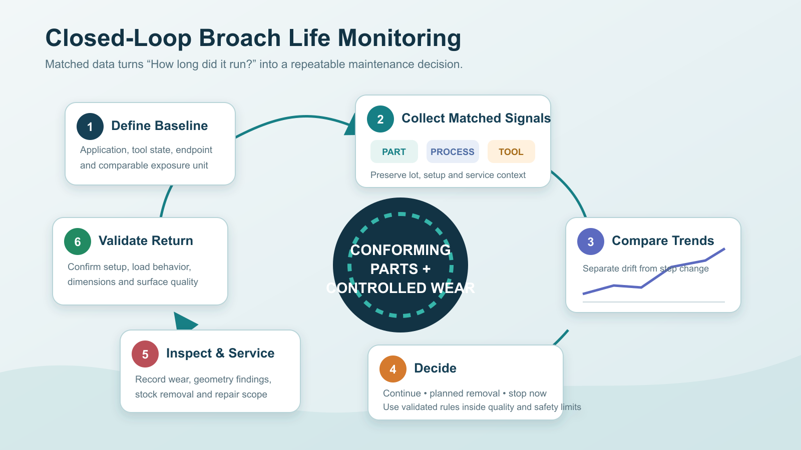
A practical loop: define the baseline, collect matched signals, compare trends, decide, service and validate the return to production.
Establish a Stable Baseline
Choose a known-good run with a conforming incoming part, verified setup, serviceable broach and controlled fluid condition. Record the part number, material lot or condition, machine, fixture, tool ID, tool service state, speed, fluid state and inspection results.
The baseline is not a permanent universal limit. It is a reference for a defined application. Reset or segment it when a meaningful input changes.
Collect Signals From the Part, Process and Tool
Part signals include feature size, profile or form results, surface finish, burrs, tearing, scoring, evidence of pickup and the pattern of any nonconformance. Do not wait for a final rejection if an in-process measurement shows a persistent drift.
Process signals may include peak and average stroke load, load shape over the stroke, cycle behavior, vibration, sound, fluid temperature and visible chip evacuation. Use signals the machine can acquire consistently. A single force value without stroke position or application context may hide which tooth section is changing.
Tool signals include wear-land development, edge rounding, adhesion, localized chipping, tooth-to-tooth differences, gullet condition, coating condition, straightness and handling damage. Inspect the entire cutting length rather than only the first visibly worn tooth.
Compare Trends, Not Isolated Readings
A load spike can come from material, chips, setup or a damaged tooth; it does not prove ordinary dullness. Poor finish may reflect adhesion, fluid delivery, incoming-hole condition or alignment. Compare matched runs and investigate abrupt steps separately from gradual wear.
Use warning and removal rules developed from process capability and tool-history evidence. The rules must remain inside the part specification and the machine/tool safety limits. If a signal changes suddenly or physical damage is found, stop and investigate rather than waiting for the trend limit.
El broaching troubleshooting guide helps separate tool, setup, machine and workpiece causes.
What Common Wear Patterns Can Tell You
Wear patterns are evidence, not automatic diagnoses.
| Observación | Possible contributors to investigate | Required response |
|---|---|---|
| Gradual, broadly uniform edge wear | Normal abrasive exposure, speed, material condition, service interval | Compare with baseline and schedule controlled removal |
| Adhesion or galling on tooth faces | Material tendency, inadequate lubricity, poor delivery, surface condition, geometry | Hold the process, remove adhered material by an approved method and correct the contributor |
| Localized chipping on one region | Misalignment, uneven stock, hard spot, chip obstruction, impact or unsupported loading | Stop; inspect tool, fixture, machine alignment and incoming part |
| Packed or damaged gullets | Excess chip volume, inadequate chip space, poor evacuation, unsuitable chip formation | Stop and clear the cause before another production run |
| Uneven circumferential wear | Eccentric pilot, guide or alignment issue, uneven hardness, bent tool | Map the wear orientation and isolate whether it follows tool, part or machine |
| Grinding discoloration or geometry variation | Incorrect prior service process | Quarantine for professional evaluation |
Continuing to run after chipping begins can convert a serviceable wear condition into a broken tooth or damaged tool body. The broach breakage prevention guide covers the wider failure risks.
Extend Broach Life in the Right Sequence
1. Remove Instability First
Verify alignment, fixture condition, guides, puller or ram condition, machine travel and repeatability. Correct abrupt load changes, chatter, impact and uneven support before changing the cutting tool specification.
2. Control the Incoming Workpiece
Hold the pilot feature, stock distribution, material condition and locating surfaces inside the agreed process window. Separate life records by materially different parts or conditions instead of averaging them together.
3. Restore Fluid and Chip Control
Confirm delivery at the cutting zone, concentration or condition, temperature, filtration and chip removal. Observe whether the full stroke receives effective flow and whether chips leave the tool without packing or recutting.
4. Optimize Parameters Within Validated Limits
Adjust speed or other application parameters one controlled change at a time. Evaluate accepted-part quality, process signals and tool inspection together. A shorter cycle is not an improvement if the stable cutting interval collapses.
5. Then Evaluate Tool Design, Grade or Coating
Once the process is stable, a design change, different tool material, heat treatment, surface treatment or coating can be compared fairly. Involve the tool and machine supplier with the part drawing, material condition, cut length, current tool history and observed failure mode. BroachingMach’s broach tools overview is a starting point for that application discussion.
6. Remove and Service Before Secondary Damage
Use the validated monitoring rules to schedule removal while wear can still be corrected without sacrificing more geometry than necessary. Preserve the service report, measurements and reason for removal. A “sharpened” status without those details is not enough for later comparison.
7. Protect the Tool Between Runs
Standardize cleaning, corrosion protection, lifting, supports, sleeves and storage. Record any drop, impact or abnormal handling event and inspect before reuse.
Create a Tool-History Record That Supports Decisions
Give every broach a unique ID and keep one continuous record through new manufacture, production runs, resharpening, coating, repair and retirement. At minimum, capture:
- Tool ID, drawing revision, material/grade and coating or treatment
- Part number, material specification, lot or condition and cut length
- Machine, fixture and setup revision
- Process settings and fluid condition
- Accepted parts, total cycles, scrap and reason codes
- Load or other monitored trend data
- Dimensional and surface results
- Inspection observations and photographs at consistent locations
- Removal date and removal reason
- Service provider, stock removed, geometry findings and repairs
- Return-to-service validation results
This record makes recurring patterns visible. If the same tooth region chips after different service events, investigate the application rather than treating each event as unrelated. If life shifts with one material lot or fixture revision, the record provides a testable lead.
Compare a Life-Extension Change Fairly
Use matched conditions and change one primary factor at a time where practical. Define the endpoint before the trial. Compare accepted output, exposure, quality trend, process stability and tool condition—not just the last part made.
For supplier or design discussions, provide the part drawing, material condition, current broach drawing, machine and fixture information, fluid data, baseline history, load trace if available, wear photographs and the exact failure or removal criterion. If the application needs a joint review, contact BroachingMach with those inputs rather than requesting a universal life estimate.
Preguntas frecuentes
How many parts should a broach produce?
There is no defensible universal count. Broach type, feature size, cut length, material condition, incoming geometry, machine alignment, speed, fluid, chip control and removal criterion all change the result. Ask for a range based on a defined application, then validate it with your own controlled history.
Is rising cutting force the best measure of wear?
It is useful when acquired consistently, but it is not sufficient by itself. Interpret the load trend with part measurements, chip behavior, material and setup changes, and physical tool inspection.
Will a harder tool material or coating always extend life?
No. Wear resistance, toughness, adhesion behavior, edge preparation, coating compatibility and resharpening requirements must match the application. Stabilize the process first, then compare the change under controlled conditions.
Should tool life reset after resharpening?
Start a new service interval, but do not erase the tool’s cumulative history. Record the resharpening event, inspection findings, stock removed and any geometry or coating changes so intervals remain interpretable.
What is the difference between predictable wear and premature failure?
Predictable wear develops gradually and consistently enough to support planned removal. Abrupt chipping, breakage, severe pickup, packed gullets, a step change in load or an unexplained quality shift is a process exception that requires immediate investigation.
Manage Broach Life as a Process, Not a Promise
The goal is not to chase the highest possible part count. It is to produce conforming parts through a stable, observable interval and remove the tool while its condition remains controllable.
Define the endpoint, record comparable exposure, monitor the part/process/tool triad, investigate abnormal patterns and improve the system in sequence. That discipline creates a defensible broach-life baseline—and a practical path to extending it without trading away quality or tool integrity.


