
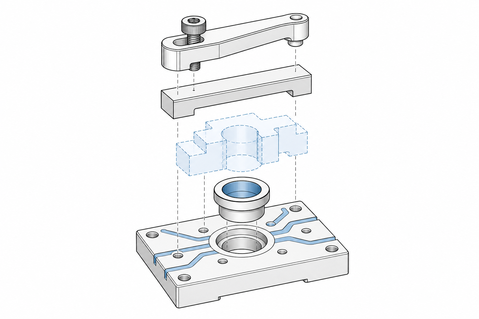
Every broaching operation stands on three legs: the machine that supplies the force, the broach that defines the geometry, and the fixture that holds the workpiece. Machine and tool get the attention; the fixture is engineered last and blamed first. In a process that cuts a finished profile in one stroke, the fixture is the only thing between tonnage-class forces and your drawing’s tolerances.
Broaching fixtures behave differently from milling or turning workholders: the cutting force is axial, unidirectional, and tonnage-class, and the cycle is short and endlessly repeated, so a fraction-of-a-millimeter defect per cycle compounds into scrap within a shift. This guide covers the loading conditions, six design principles, internal versus surface fixtures, workpiece-family architecture, failure modes, and what belongs in a fixture RFQ.
Why Broaching Fixtures Are Different: Tonnage-Class Force on a Fast Cycle
Broaching discards the assumptions of most fixture literature: moderate, multi-directional milling forces spread over seconds or minutes. The entire metal-removal load acts along one axis at full magnitude from the first engaging teeth to the last, and on production parts that force is measured in tons; sizing it is covered in our article on Cómo calcular la capacidad de carga de una máquina de brochado. To the fixture, that force wants to lift, tilt, or crush the workpiece; every load path must deliver it into the machine table, not the part.
The second condition is repetition: a production fixture cycles more in a month than a job-shop fixture sees in years. These conditions reduce fixture design to three themes. Rigidity — the force path from workpiece through locators into the bed must be short and stiff: compliance under tonnage is lost tolerance. Datum integrity — the part must sit identically relative to the broach, every cycle, for the tool’s life. Chip management — chips and coolant must leave the cutting zone, not trap on a locating face.
Six Principles of Broaching Fixture Design
1. Unify your datums: design datum = locating datum = measuring datum
A broached feature is only as accurate as its datum chain: the drawing defines the feature from certain datums, the fixture must locate on those datums, and inspection must measure from them again — every transfer adds error no machine can remove. If a keyway is called out from the bore, the fixture orients from that bore; if referenced to an end face, the part seats on that face. Datum unification is free at design time, impossible to retrofit, and prevents parts that pass the CMM but will not assemble.
2. Let the axial force clamp for you — but check the direction first
Because broaching forces are predictable in direction, the fixture can be arranged so the cut presses the workpiece into its locators instead of pulling it away. On a vertical pull-down internal machine, the broach descends and the reaction pushes the part onto the seat below — the stroke does most of the clamping. On a pull-up machine the same reaction lifts the part, so the locating seat must be inverted, with the part registered against a facing surface above it. Identical parts, opposite fixtures: stroke direction is a first-order design decision. When the geometry works with you, external clamps only prevent side shift and rotation, and small clamp force means small distortion; the machine-side picture is in our surface broaching machine guide.
3. Provide clearance and overtravel for the whole broach, not just the cut
The fixture must accommodate the broach’s entire journey: approach, cut, exit, and overtravel past the last tooth. Too little clearance and a clamp arm, locator edge, or guard bracket enters the broach’s path — the collision destroys an expensive tool in milliseconds; too much open space and the fixture loses the close support the cut needs. Map the full swept envelope, pull head included, against the longest and shortest tool variants in the plan — a stroke ending flush with the fixture edge has no margin for regrinds or longer replacements.
4. Engineer the chip and coolant path as deliberately as the load path
A fixture that traps chips — in a pocket behind the part, on a horizontal locating face, around a bushing — will eventually compress them into a datum surface, and a workpiece seated on a chip is seated high. Tilt datum faces where possible, machine flush-out reliefs around nests and supports, eliminate horizontal ledges near the cutting plane, and aim coolant at the cutting zone and the seats. Chip load per tooth and stroke speed set how much chip must clear per second, so fixture and tooling must be designed together — a fixture designed in isolation gets the escape path wrong.
5. Design for quick change: indexing, multi-station loading, foolproofing
Because cutting cycles are short, load and unload time can dominate the total cycle. Standard answers: two-position indexing so the operator loads one station while the machine cuts the other, pass-through ejection so parts fall clear, and quick-change clamps sized for the repeatability the tolerances need. Make wrong loading impossible rather than unlikely — asymmetric locating patterns, mismatched pin diameters, a physical block where a symmetric part would otherwise fit backward. Foolproofing is far cheaper than the quality hold that follows a reversed batch.
6. Plan for broach breakage: contain the energy
A broach under load is a stored-energy system; when one breaks, the pieces do not politely fall. The work zone needs engineered containment: guarding around the stroke axis, and sacrificial elements so a released tool’s first impact is a replaceable bumper, not the machine ways, pull head, or an operator station. Full-support locating also lowers breakage risk by keeping the part from cantilevering under cut. Interlocks — guards that stop the stroke, part-presence sensing against dry strokes into misloaded blanks — belong in the fixture, not a controls afterthought.
Internal Broaching Fixtures: Bushings, Pilots, and Face Support
Internal broaching — keyways, splines, and profiles inside a bore — imposes two jobs: hold the part square to the stroke axis, and support the end face against the full axial pull. The characteristic component is the guide bushing: it aligns the part to the broach (in many keyway jobs the finished bore itself is the guide) and absorbs the radial components of cutting force before they reach the teeth as bending. Tooling practice for the most common case is in our keyway broaching set guide.
A fixed bushing is rigidly mounted and enforces a defined tool-to-part relationship; it suits work where the feature positions relative to something other than the bore, and multi-part fixtures sharing a stroke. A floating bushing self-aligns within a small range, letting the part settle onto the broach when bore and seat are not perfectly square, protecting the tool from side load and the part from distortion. The rule: the drawing locates from the bore, a floating guide suffices; the drawing locates from an external datum, a fixed reference must carry it. This is linear-broaching territory — rotary broaching instead starts from a shallow pilot hole in the part face, a contrast explained in our rotary broaching pilot hole guide.
The end face support is the other half of the fixture. The full cutting force ends as compression between the workpiece face and the fixture seat, so that seat must be hardened, flat, and generously sized — a thin washer-like support behind a heavy pull will brinell and dish. When the end face is not square to the bore, a fixed seat forces the part to tilt or the broach to bend — the case for a self-aligning seat paired with a floating guide. An annular chip relief around the bore opening keeps chips from trapping between part and seat.
Surface Broaching Fixtures: Datums, Clamp Placement, and Thin-Wall Support
Surface broaching cuts open profiles — slots, flats, faces, contours — and its fixtures carry two broaching-specific obligations. The first is datum strategy: the profile is positioned relative to the part’s primary datums, so the fixture locates from those datums with hard stops on the faces that matter. And because the cutting force has a large component normal to the cut, orient the part so that component drives it onto solid support, not a clamp span.
The second obligation is keeping every clamp out of the tool’s swept envelope. A surface broach passes the whole cut at speed; a clamp overhanging the profile even slightly is a guaranteed tool wreck. Workable patterns: side clamping, clamps on finished surfaces clear of the path, and swing or drop-in designs retracting fully below the cutting plane. Clamp placement follows the broach envelope first, clamping efficiency second — one more reason the fixture cannot precede the tooling layout.
Thin-wall parts get their own paragraph because they are where surface fixtures quietly fail. A wall flexible in the cutting-force direction deflects under load and springs back after the cut, leaving geometry that varies however rigid the fixture body is. The remedies are standard: auxiliary supports behind the flexible region, so the cut works against a support instead of a span, and clamp points aligned directly over locators so force does not bow the part.
Fixturing by Workpiece Family: Disks, Shafts, and Irregular Parts
Disk-shaped parts: gears, pulleys, sprockets
Disks are the friendliest family: a finished bore plus one square face is a complete locating scheme, and the bore often doubles as the broach guide. The fixture is typically a hardened support ring or pedestal whose face seats the part and whose bore closely fits the part bore — the classic keyway or spline setup on gear blanks. What separates good from marginal: support-ring hardness and flatness under repeated tonnage, a close non-binding bore fit, positive angular orientation to an OD feature where the keyway must clock (a notch, pin, or cast lug, not friction), and chip escape around the seat.
Shafts: keyways and flats on cylindrical stock
Shaft work swaps pedestals for axial supports: V-blocks or matched half-bushings carrying the cylinder, an end stop setting axial position, and anti-rotation often belonging to the cut itself, since a broach piloted in a guide bushing controls its own angular position. The recurring problems: deflection on long slender parts (answer: intermediate supports close to the cut) and end-stop wear from parts rammed home every cycle (answer: a hardened, replaceable stop face).
Irregular parts: connecting rods, shift forks, levers
Irregular forgings and castings are where broaching fixture design earns its fee. With rarely a convenient flat or concentric surface to build from, the fixture becomes a nesting structure registering the part on its functional datums — for a connecting rod, the big-end and small-end bores plus a face; for a lever or fork, the hub bore plus a cast or machined reference. We walk through the rod case, fixturing included, in our brochado de bielas article, and the same hub-bore thinking appears in the fixturing section of our gear shift fork case study. The lesson from both: locate from the features the drawing names, and never clamp on a draft surface that varies casting to casting.
Common Fixture Failure Modes and What to Do About Each
Clamping distortion shows up as dimensions that pass unloaded and fail loaded
The signature: a part that measures in tolerance but drifts as clamping or cutting deflection varies — or a feature consistent but consistently wrong because the part was bowed while cut. The mechanism: clamping force landing where the part has no support — a clamp overhanging a locator, a thin wall squeezed between stop and clamp. Countermeasures are structural: put clamps over supports, add supports under spans, and exploit the stroke’s axial self-clamping so external force stays minimal. When distortion is suspected, measure the part in the fixture before unclamping — it separates fixture error from tool error in minutes.
Datum wear shows up as slow drift, not sudden scrap
Locating faces and bushings wear: each load cycle slides the part across a stop, escaped chips act as abrasive between part and seat, and bushing bores open and go oval under years of tonnage. The symptom is a feature that creeps out of position over weeks while first-piece checks keep passing. The defenses are hardness and monitoring: hardened, ground locating elements, replaceable wear pads, bushings as consumables with spares stocked, and a dimensional trend chart treating datum wear as a process input. When a broached feature trends on one machine with one fixture, measure the fixture before blaming the tool regrind.
Chips on the locating face show up as a batch of parts seated high
A single chip under a workpiece lifts it, shifting every feature cut in that stroke, and the operator cannot see it — scrap in batches, the most expensive failure on this list. Countermeasures layer: geometry first (tilted seats, relief grooves, no ledges near the cut), then flushing (coolant or air at the seats during loading), then detection (seat-condition sensing on high-volume lines, or a visual check before every load). If a fixture repeatedly traps chips in one spot, fix the fixture; diligence cannot outperform geometry.
Insufficient clearance shows up as a broken broach
When a broach strikes fixture steel, the broach loses — and a broken production broach is among the most expensive events in a broaching shop: the tool, the downtime, often the part, sometimes the pull head. The usual causes are change management: a clamp adjusted into the envelope, a longer broach fitted without re-checking, a fixture rebuilt slightly differently after maintenance. Countermeasures are procedural as much as geometric: sweep the full tool envelope at design against the actual tool drawing, re-verify after any tool change altering length or shank, run first strokes at reduced speed with guards active, and keep sacrificial bumpers replaceable.
Inspecting and Maintaining Broaching Fixtures
A production fixture is a wear system and deserves a schedule written like one. The core routine is periodic requalification of everything carrying tolerance: seating-face flatness and condition, locator and stop position and wear, bushing bore condition and concentricity. The interval can be calendar-, cycle-count-, or — best — part-statistic-based, with wear limits set in advance so “still usable” is an engineering call, not production pressure. Two practices make it stick: a fixture record (what produced, when last qualified) and stocked wear parts — a fixture down three days waiting on a bushing is a line down three days.
In-House vs. Outsourced Design — and What a Fixture RFQ Should Contain
Shops with tooling capability and a family of similar parts often do best designing in-house: they own the part knowledge, and each fixture makes the next cheaper. Outsourcing earns its place for one-off complex workholders, shops without broaching-specific experience, or fixtures bought as part of a machine-and-tooling package that must match interfaces the builder controls. A middle path works well too: design the locating scheme and force path in-house, contract the detail design and build to a tooling house. Either way, fixture quality tracks design-input quality — an RFQ a builder can quote from contains, at minimum:
- The workpiece drawing set — part print with tolerances and datums, material spec, and the heat-treatment condition the part arrives in.
- Volume and cycle targets — parts per hour and per year, load-unload method, and changeover needs between variants.
- The machine interface — which machine it mounts on, table size and mounting pattern, pull head or tool interface, stroke length, force rating.
- The tooling definition — broach drawing, or at minimum tool length and shank, since the fixture envelope follows the tool.
- Datum and measurement plan — how the feature will be inspected, so fixture and inspection schemes agree from day one.
- Chip and coolant conditions — available coolant pressure and volume, and how chips are cleared from the cell.
A supplier who receives all six can quote a fixture that keeps working; one who receives half quotes assumptions. To see how a supplier approaches machine, tooling, and fixture as one system, our fixture design and build service page describes the process and the information we ask for.
FAQ: Broaching Fixture Design
How is a broaching fixture different from a milling fixture?
The force scale and direction. Broaching delivers tonnage-class force along one axis at high repetition, so the fixture is built around a short stiff load path, seats the stroke itself clamps against, and wear surfaces rated for millions of cycles. A milling fixture sees smaller, multi-directional, interrupted loads; designs transplanted between the two underperform both ways.
When should an internal broaching fixture use a floating bushing?
Use a floating guide when the drawing locates the feature from the bore and incoming parts have some runout between bore and seat — the float lets each part settle onto the broach without side-loading the tool. Use a fixed bushing when the feature must hold position relative to an external datum, or when several parts share one stroke. If a fixed bushing is specified to “fix” a parts squareness problem, the honest answer is usually to fix the upstream operation instead.
How often should fixture locating faces and bushings be checked?
No universal number exists — it depends on cycle count, material, and chip abrasiveness — but a good program is constant in structure: qualify at build and first article, requalify on a schedule or whenever part trends move, and set wear limits in advance for every replaceable element. Trending part dimensions is the cheapest early warning: datum wear shows up in parts long before it is visible on the fixture.
Can one fixture handle several part variants?
Often, with discipline about which variants are grouped. Parts sharing a locating scheme and tool envelope, differing only where the fixture does not touch, are good candidates; interchangeable locator blocks, nests, and stops turn one base into a family toolholder. Grouping fails when parts differ in primary datums or need different broach envelopes, because every compromise lands in tolerance.
If you are planning a broaching operation, or retrofitting fixtures on a line that keeps drifting, the fixture deserves the same engineering attention as machine and tool. That is a service we provide directly: send the prints, volumes, and machine details from the RFQ list above, and we will build workholding that settles datums, force path, and chip management before anything is cut. Start on our fixture design and build page, or send your workpiece details straight to our engineering team.


