
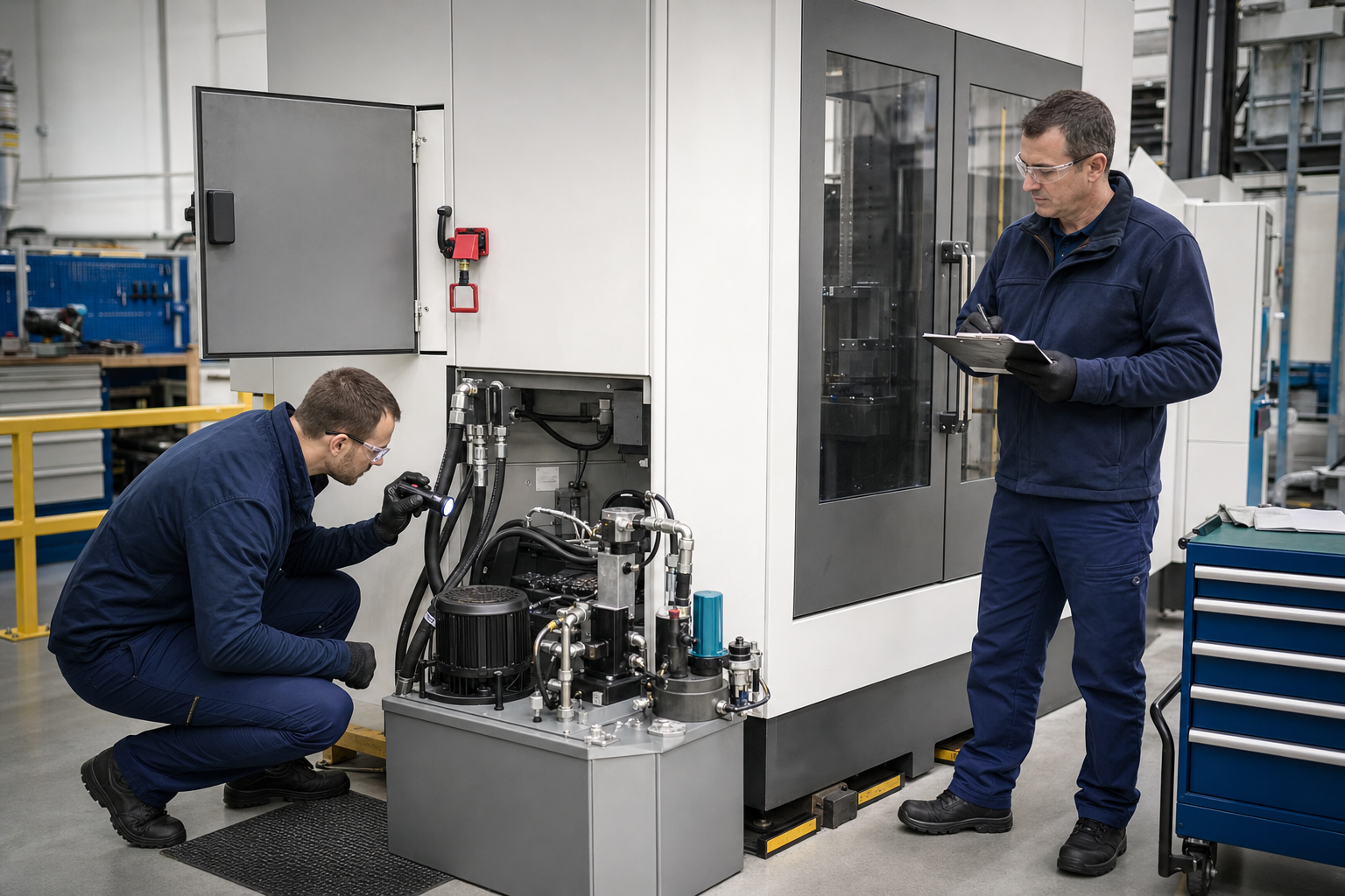
Conceptual illustration of a locked-out broaching machine inspection. It is not a photograph of a BroachingMach service visit and does not replace the machine-specific manual or site safety procedure.
A broaching machine preventive maintenance checklist should protect four things at the same time: people, machine condition, broach-tool loading and part quality. Cleaning chips and checking oil are important, but they are not a complete maintenance program.
The schedule below is an equipment-neutral starting framework for vertical, horizontal, hydraulic and servo-controlled broaching machines. The machine builder's manual, lubrication chart, component documentation, local regulations and risk assessment always take priority. Convert this framework into machine-specific tasks, limits, owners and records before use.
Start With the Machine Manual and Asset Baseline
Before setting frequencies, collect:
- Machine manufacturer, model, serial number and control version
- Current operator, electrical, hydraulic and lubrication manuals
- Lubricant, hydraulic-fluid and coolant specifications
- Safety-device and lockout/tagout requirements
- Rated force, stroke, speed and permitted tooling envelope
- Hydraulic and electrical drawings
- Critical alignment and inspection procedures
- Current spare-parts list and supplier contacts
- Known load, cycle-time and part-quality baseline
- Previous maintenance, alarm and repair history
Do not copy a pressure, filter interval or alignment tolerance from another machine. Even machines with similar tonnage can use different pumps, valves, guides, sensors, lubrication systems and control logic.
El broaching-machine operating guide provides broader startup and operating context. Maintenance tasks should be integrated with the approved operating procedure rather than kept as a separate form nobody uses.
Maintenance Roles and Safety Boundary
Operator Checks
Operators can normally perform external visual checks, housekeeping, fluid-level observation, abnormal-noise reporting, tooling checks and approved lubrication tasks defined in the manual. They should know the normal load, sound and cycle behavior well enough to stop when the process changes.
Trained Maintenance Tasks
Qualified maintenance personnel handle guarded areas, electrical cabinets, pressure checks, filters, hose replacement, sensor verification, alignment procedures and component service according to the site program.
OEM or Qualified Service
Machine geometry restoration, control changes, hydraulic-system repair, safety-circuit validation, structural inspection and major rebuild work may require the manufacturer or a qualified specialist.
Never reach into the cutting or tool-return area, open an energized cabinet, loosen a pressurized connection or bypass a safety interlock to finish a checklist. Apply the approved lockout/tagout and stored-energy procedure before work that requires access.
Maintenance Frequency Map
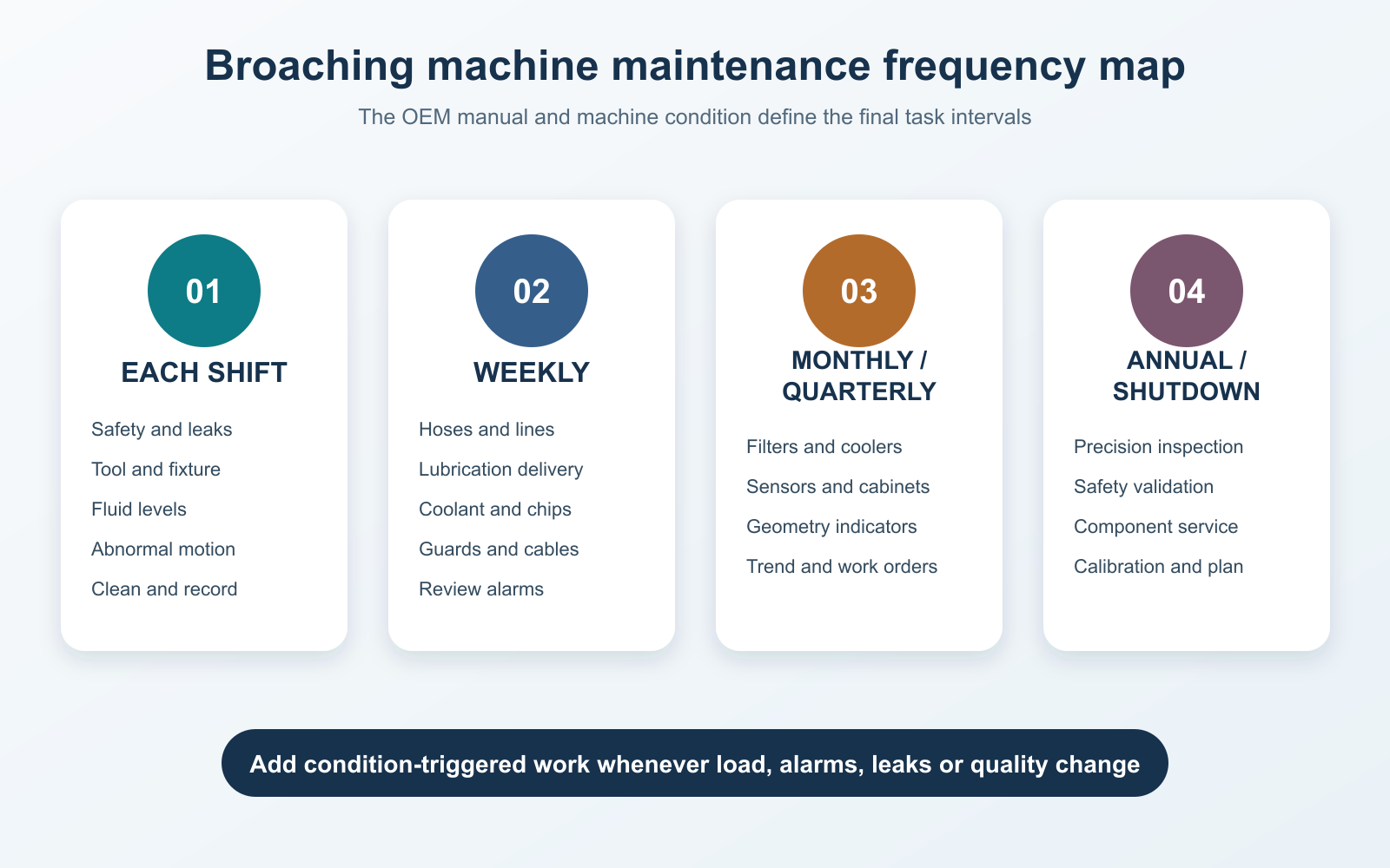
Frequencies are a starting framework. Adjust them using the OEM manual, duty cycle, environment, condition trend and maintenance history.
| Frequency | Primary objective | Typical owner |
|---|---|---|
| Pre-start / each shift | Detect unsafe or abnormal condition before production | Operator |
| Daily / end of shift | Clean, record and restore the normal operating state | Operator |
| Weekly | Inspect recurring wear, leaks, fluid delivery and guarding | Operator + maintenance |
| Monthly / quarterly | Test systems, inspect filters, connections, geometry indicators and records | Trained maintenance |
| Annual / planned shutdown | Perform deeper inspection, calibration and component service | Maintenance + qualified service |
| Condition-triggered | Respond to load, leak, alarm, vibration or quality change | Defined escalation team |
Calendar frequency alone is not enough. A machine running three shifts in abrasive cast-iron chips needs a different program from a lightly used machine in a controlled toolroom. Track operating hours, cycles, material, environment and unplanned events.
Pre-Start and Each-Shift Checklist
Before the first production stroke:
Safety and Work Area
- Confirm guards, doors, barriers and interlocks are in their normal approved condition.
- Check that the work area, platform, stairs and access routes are dry and clear.
- Verify emergency stops and safety devices according to the approved test procedure.
- Confirm no maintenance locks, tools or loose objects remain in the machine.
- Inspect lighting and visibility around loading, tooling and chip areas.
Machine Condition
- Look for fresh hydraulic, lubrication or coolant leaks.
- Check externally visible hoses, tubes, fittings and cables for abrasion, looseness or damage.
- Confirm fluid levels are within the machine-specific range.
- Inspect guides, pull heads, retrievers and work supports for visible damage or contamination.
- Confirm limit devices, stops and sensors are secure and unobstructed.
Tooling and Workholding
- Identify the correct broach, holder, puller, fixture, guide and program.
- Inspect broach edges, pilots, pull end and chip spaces before installation.
- Clean fixture datums, support faces and guide surfaces.
- Verify clamps and fasteners are present and secured by the approved method.
- Confirm the workpiece enters the guide and fixture without forced misalignment.
Trial Cycle
Run the approved empty or setup cycle only where the manual permits it. Watch for abnormal motion, noise, leakage, delayed sensor response or unexpected alarms. The first production part should receive the defined first-off inspection.
Daily and End-of-Shift Checklist
- Remove chips from approved collection points without driving debris into guides, seals or electrical areas.
- Clean exposed fixture and support surfaces.
- Return the ram, slide, puller or tool-handling system to the specified safe position.
- Inspect the broach for pickup, packed chips, edge damage and abnormal wear.
- Check coolant flow and nozzle direction.
- Observe lubrication-system status and approved indicator points.
- Record peak load or machine feedback for the run where available.
- Record alarms, rejected parts, unusual sound, vibration, leakage and operator interventions.
- Protect removed broaches in suitable racks, sleeves or supports.
- Leave platforms, guarding and access routes clean.
Compressed air can drive chips into seals, ways, bearings and electrical components. Use only the cleaning method approved for the machine and material.
Weekly Checklist
Hydraulic and Lubrication Systems
- Inspect hoses, fittings, manifolds, cylinders and visible seals for leakage or abrasion.
- Check oil appearance for unexpected foam, cloudiness, odor or contamination.
- Confirm reservoir breather and external surfaces are not blocked by debris.
- Inspect lubrication lines and distribution points for damage or missed delivery.
- Review automatic-lubrication alarms and consumption trend.
Do not top off repeatedly without finding the source of fluid loss. The existing guide to common hydraulic broaching-machine failures provides symptom context; opening or adjusting a hydraulic system still requires qualified personnel.
Coolant and Chip Control
- Inspect coolant level, concentration or condition using the approved method.
- Clean accessible strainers, screens and chip containers as specified.
- Confirm nozzles deliver fluid to the intended cutting zone.
- Check that chips are not accumulating around sensors, guideways or tool-return paths.
- Review filtration pressure or status indicators where installed.
Coolant selection is application-specific. Review the broaching cutting-fluid guide when material, tool coating or surface problems change; do not substitute a generic fluid based only on appearance.
Mechanical and Safety Inspection
- Inspect accessible fasteners, guards, covers and platforms for looseness or damage.
- Check puller, retriever, guide and fixture interfaces for abnormal marking.
- Inspect cable carriers and flexible lines through their visible travel.
- Review emergency-stop and interlock test records.
Monthly and Quarterly Checklist
Use the machine manual to assign actual intervals.
- Review hydraulic and lubrication filters using indicators, samples or specified service criteria.
- Check reservoir condition, breathers, coolers and heat exchangers.
- Inspect electrical-cabinet seals, fans and filters with power isolated by qualified personnel.
- Examine terminals, connectors, sensors, switches and cable routing for heat, looseness or contamination.
- Verify pressure, temperature, flow and level instruments against the approved method.
- Check ram, slide, guide, faceplate, puller and fixture alignment indicators.
- Inspect cylinders, rods, seals, bearings, ways, screws or drive elements applicable to the machine.
- Review control backups, alarm history and parameter-change records.
- Inspect anchoring, foundation interfaces and structural fasteners where specified.
- Confirm lifting, tool-handling and work-loading aids remain safe and suitable.
- Audit the preventive-maintenance log for repeated defects and overdue corrective actions.
Geometry checks must use the manufacturer's test bar, datum and procedure. A part-quality problem should not be “corrected” by an undocumented machine adjustment.
Annual or Planned-Shutdown Checklist
A planned shutdown allows work that cannot be performed safely during production:
- Complete the manufacturer-defined precision and alignment inspection.
- Service hydraulic fluid, filters, pumps, valves, accumulators, seals and coolers based on condition and the manual.
- Inspect servo drives, motors, couplings, screws, gearboxes or mechanical transmissions as applicable.
- Validate safety circuits, stops, guards and interlocks using the approved test protocol.
- Inspect electrical cabinets, grounding, cooling and control backups.
- Inspect structural members, ram/slide guidance, pull heads and high-load interfaces.
- Calibrate relevant pressure, force, position, temperature and part-inspection devices.
- Review spare parts for aging, storage condition and obsolescence.
- Close recurring corrective actions and update the maintenance plan.
Fluid replacement should follow oil analysis, component requirements and the manufacturer's interval—not a universal number copied from the internet.
Hydraulic vs Servo and Mechanical Tasks
Hydraulic Machines
Priorities include fluid cleanliness, leaks, hoses, seals, pumps, valves, cylinders, temperature control, filters and pressure instrumentation. Foam, unexpected heat, slow motion and unstable force require investigation.
El hydraulic broaching guide discusses machine-specific operating and maintenance points. Use it as supporting context, while the actual manual governs the installed system.
Servo or Electromechanical Machines
Priorities shift toward servo alarms, motor temperature, encoder feedback, cables, couplings, screws, guides, lubrication and control backups. Do not apply hydraulic tasks to a machine with no hydraulic power unit.
Mechanical and Legacy Machines
Clutches, brakes, gears, chains, belts, bearings, lubrication and mechanical stops may require model-specific inspection. Missing documentation is itself a maintenance risk; locate the correct manual and establish safe service procedures before intrusive work.
Condition Monitoring and Escalation
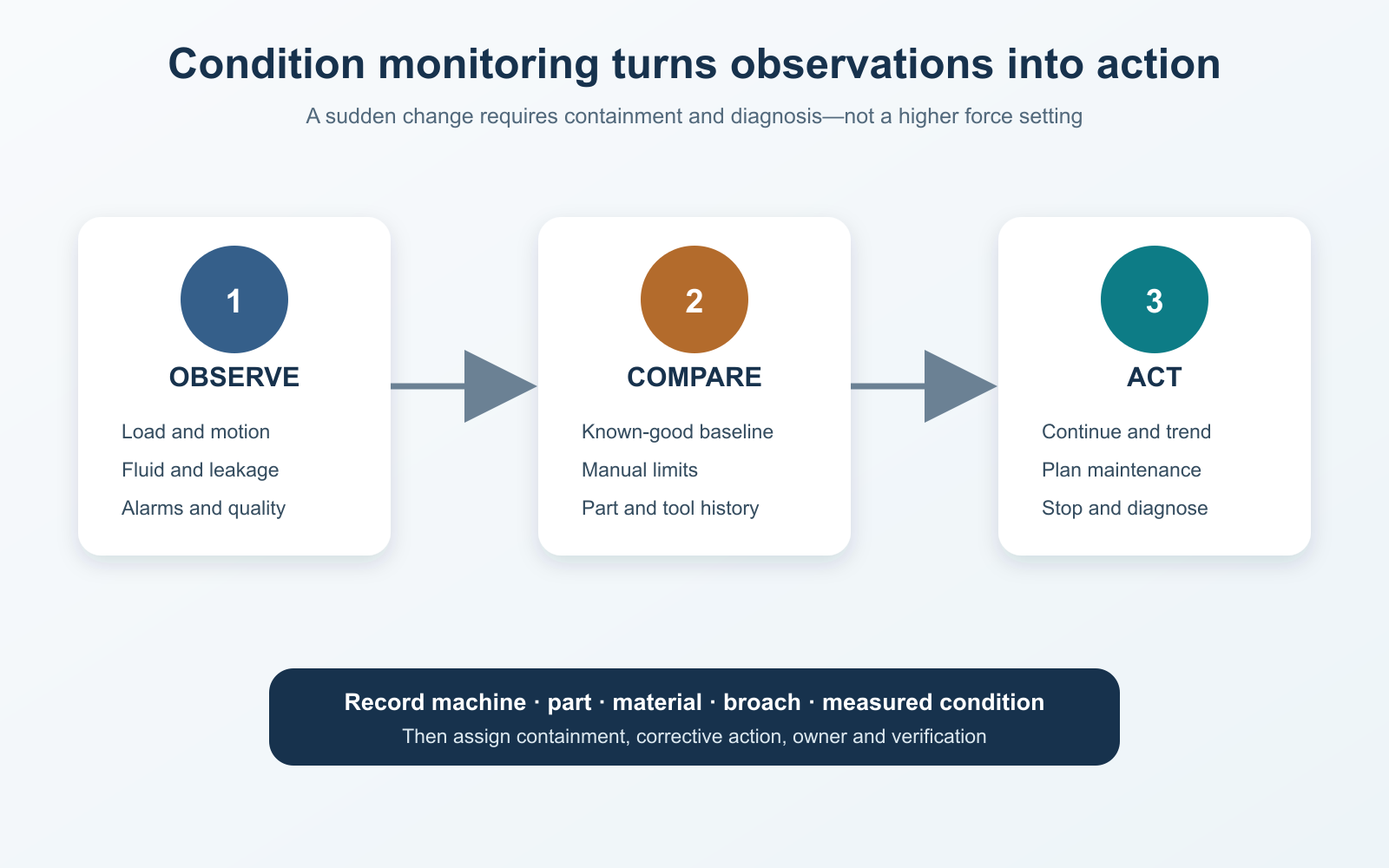
Use load, motion, fluid, alarm and part-quality trends together. A sudden change should trigger containment and diagnosis, not a higher force setting.
Track:
- Peak force, pressure, motor current or servo load
- Load profile through the cutting stroke
- Cycle time and return time
- Hydraulic or drive temperature
- Fluid condition and filter indicators
- Lubricant consumption
- Leakage observations
- Alarm frequency
- Tool-change and resharpening history
- Part size, finish, burrs and scrap
Set alert and stop limits from a known-good baseline, component requirements and process history. If load changes suddenly, hold the process and inspect material, pre-bore, tool, chips, alignment, fixture and fluid delivery. The broaching troubleshooting guide helps separate tool, workpiece and machine causes.
Maintenance Record Template
| Field | Récord |
|---|---|
| Machine / serial number | Unique asset identity |
| Date, shift and operating hours/cycles | Exposure |
| Part, material and tool ID | Process context |
| Task and manual reference | What was checked |
| Observed value or condition | Evidence, not “OK” alone |
| Normal range / acceptance source | Manual, procedure or baseline |
| Defect and immediate containment | Safety and production response |
| Work order / corrective action | Ownership |
| Parts and fluids used | Traceability |
| Completion and independent verification | Closure |
Attach photographs, oil-analysis results, load traces, alignment reports and replaced-component data where useful. Repeated “adjusted” entries without measurements often hide a developing problem.
Escalate Instead of Continuing Production When
- A guard, interlock, emergency stop or safety device fails a test.
- A new or increasing hydraulic leak appears.
- Motion is jerky, delayed, uncontrolled or different from the validated cycle.
- Load, pressure, current, temperature, sound or vibration changes abruptly.
- The broach, pull end, guide, holder or fixture shows damage.
- Workpieces lift, bind, drift or require force to load.
- Multiple parts show a new size, finish or burr defect.
- Chips block the tool path or return mechanism.
- A sensor or stop is loose, damaged or bypassed.
- The machine has had an overload, collision, jam or uncontrolled stop.
Do not simply clear the alarm. Record the event, contain affected parts and identify the cause before restart. The broach breakage guide explains why load, alignment, tool condition and handling must be considered together.

BroachingMach hydraulic double-cylinder pull-down internal broaching machine. It is shown as one real machine configuration; maintenance points and intervals must be taken from the exact model, installed components and operating manual.
Preguntas frecuentes
How often should a broaching machine receive preventive maintenance?
Use pre-start and daily operator checks plus periodic trained-maintenance tasks, but set actual intervals from the machine manual, hours/cycles, environment and condition history. There is no universal schedule for every broaching machine.
What should be checked every day?
Safety devices, leaks, fluid levels, visible hoses/cables, tooling, fixture cleanliness, chip accumulation, lubrication/coolant status and abnormal load, noise or alarms should be covered by the machine-specific daily procedure.
Is hydraulic oil level enough to judge system health?
No. Condition, contamination, temperature, aeration, filtration, leaks and component behavior also matter. Repeatedly adding oil without locating the loss can conceal a fault.
Can operators perform all maintenance?
No. Operator inspections should be clearly separated from trained maintenance, electrical work, pressurized-system service, geometry correction and qualified machine service.
What maintenance data is most useful?
Measured condition linked to machine, part, tool and time is more useful than a simple check mark. Load profiles, alarms, fluid results, alignment measurements, photographs and corrective-action records build a usable history.
Does preventive maintenance replace troubleshooting?
No. Maintenance reduces avoidable failures and establishes baselines. When a new symptom appears, use a controlled diagnostic process and contain affected production.
Turn the Generic Checklist Into a Machine-Specific Program
This framework becomes useful only after every task has a machine reference, frequency, safe method, acceptance limit, owner and escalation route. Start from the installed manual, then adjust using real duty cycle, environment, load and quality history.
Review the BroachingMach machine range for configuration context. For model-specific manuals, service scope or an engineering review, contact BroachingMach with the machine model, serial number, control, symptoms and maintenance history.


