

Non-dimensional engineering concept. It is not a customer drawing, a BroachingMach measurement cell, a calibrated result or proof that one inspection method accepts every internal spline.
Internal spline inspection starts with the acceptance question, not with a preferred gauge. A production team may need a quick functional answer—does the specified mating condition pass? A quality or engineering team may instead need a diagnostic answer—what profile, lead, index, tooth-space, bore or datum relationship explains a result? Those are related, but they are not the same inspection job.
This guide explains how to build a drawing-led inspection plan for an already specified internal spline. It does not select a standard, prescribe numerical limits, recommend a gauge supplier or claim that BroachingMach performs calibration or metrology services. The drawing owner and the qualified inspection authority remain responsible for the governing document, acceptance method and correlation plan.
For process and tooling fundamentals, see Spline Broaching: The Complete Guide. For a transmission-gear route in which heat-treatment stage, fixture and release planning affect the inspection sequence, see Transmission Gear Internal Spline Broaching.
The Short Answer
Use a functional verification method when the released requirement is to confirm a defined mating or assembly condition. Use analytical measurement when the team must understand the geometry, datum relationship or source of a nonconforming result. Many controlled routes need both: a functional check for acceptance and an analytical method for first article, investigation, process change or correlation.
Neither method replaces the other automatically. A successful functional check does not describe every geometric characteristic, and a detailed profile report does not by itself prove that the agreed mating condition has been reproduced. The controlled drawing and customer acceptance method decide what evidence is required.
1. Freeze the Inspection Definition Before Measuring
An internal spline may be described by a drawing, a model, a specification, a customer standard, a mating component or a combination of these. Before selecting an inspection route, make the inspection definition explicit.
Record and review:
- the controlled drawing or model revision;
- the governing standard or customer-document revision, where one is named;
- the spline form and the exact feature boundary;
- the functional bore, face, axis and angular datums;
- the production stage: pre-broach, immediately after broaching, after heat treatment, after finishing or final release;
- the required acceptance result and the party authorized to interpret it;
- the mating-part or functional-reference condition, when functional fit is required.
A part description such as “internal spline” is not sufficient. A similar-looking form may use a different datum map, acceptance rule, material condition, production stage or mating requirement. The inspection plan must follow the released definition for the actual part.
Build an inspection record that can be read later
The record should make the result reproducible without pretending that every production check is a laboratory study. Identify the part and drawing revision, the production stage, the method category, the datum setup, the reference used, the person or system authorized by the quality plan, and the disposition. When a method is used for trend control rather than final acceptance, label it that way.
This distinction is practical. It prevents a later team from treating a setup check, a tool-condition observation or an in-process process signal as though it were the customer’s final functional acceptance result. It also makes an engineering investigation faster because the result can be connected to the correct material state, fixture condition and inspection reference.
2. Functional Verification and Analytical Diagnosis Answer Different Questions
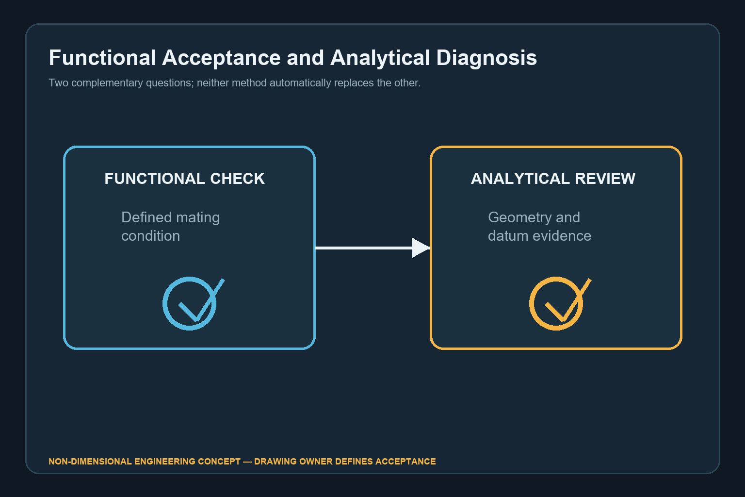
The diagram separates acceptance and diagnostic questions. It does not rank methods or imply that a measurement result can be transferred between drawings, suppliers or mating parts without correlation.
Functional verification
Functional verification asks whether the part satisfies an agreed use-related condition. Depending on the released requirement, a controlled composite or limit-style method may screen the combined effect of multiple feature characteristics in a practical assembly-oriented check.
Its strength is that it can align with the defined function when the reference condition, method and acceptance authority have been agreed. Its limitation is equally important: a pass or fail alone may not reveal which individual geometric condition caused the result, nor whether a different mating reference would behave the same way.
Analytical diagnosis
Analytical measurement asks for a geometric explanation. It can be used to examine the relevant profile, lead, index, tooth-space, diameter, runout or datum relationship that the drawing requires. Dedicated spline or gear measurement systems, form-measurement approaches, CMM-based methods and other controlled techniques may be candidates depending on access and the defined characteristic.
Analytical evidence is useful for first-article review, tool/process development, supplier correlation and troubleshooting. It still needs a controlled setup, a known datum strategy, a qualified method and an agreed interpretation. A detailed report cannot substitute for an agreed functional-acceptance check merely because it contains more numbers.
Use the two methods together when the release plan requires it
A sensible plan can use functional verification to confirm the released acceptance condition and analytical measurement to establish a baseline, investigate a change or resolve disagreement. The sequence should be established before a production dispute, not improvised after parts have been mixed.
3. Choose a Measurement Category by the Question It Answers
The categories below are planning options, not recommendations for a particular instrument. The qualified inspection function must confirm the method, governing document, setup and correlation evidence for the actual drawing.

Non-dimensional datum concept. The drawing owner must define the actual datum references and controlled characteristics for the part.
| Measurement category | Primary question it can help answer | Boundary to retain |
|---|---|---|
| Functional or composite check | Does the part satisfy the agreed mating or limit-style acceptance condition? | It may not isolate the individual feature characteristic that produced a result. |
| Pins, balls, span or related indirect methods | Can a defined local or derived characteristic be compared to the released method? | The exact setup, feature form and calculation basis must come from the controlled requirement. |
| Dedicated spline or gear metrology | Which specified profile, lead, index or related characteristic needs diagnostic evidence? | Select the method only after confirming access, datum and the governing definition. |
| CMM or form measurement | Can the required feature/datum relationship be evaluated using an agreed strategy? | Probe access, alignment and uncertainty must be controlled by the responsible quality system. |
| Visual, burr and surface review | Is the feature free from the drawing-defined visible condition or protected-zone issue? | It does not replace form, fit or datum verification. |
The table is a decision aid, not a gauge specification. A method can be technically capable yet still be the wrong acceptance method if it does not reproduce the released datum and functional intent.
Accessibility changes the measurement plan
Before selecting a category, confirm what the measurement interface can actually reach. A long internal form, a shoulder near the opening, a restricted bore, a protective surface, a post-process burr condition or a required free-state presentation can change which method is repeatable. Do not solve an access limitation by redefining the characteristic after the fact.
When access is constrained, retain the original acceptance question and escalate the method decision to the drawing owner and qualified inspection function. A convenient measurement that does not reach the specified reference may be useful process information, but it is not automatically an approved substitute.
4. Keep the Datum Strategy Continuous Through the Route
The same part can be located differently during broaching, heat treatment, finishing and inspection. That may be necessary, but it must be understood. If the broach is guided from a prepared bore while final acceptance is related to a face, pilot or mating axis, the plan needs a documented relationship between those references.
Ask these questions before treating an inspection result as a tool or machine problem:
- Which bore, face, axis or angular relationship is the drawing's functional reference?
- How is that reference established during the selected inspection method?
- Was the part allowed to unload before final measurement where the requirement expects a free-state condition?
- Did a material or heat-treatment stage change the feature or datum relationship after broaching?
- Is the result being compared with a customer/mating method that has been correlated to the supplier method?
The broach, guide, fixture and inspection plan should be reviewed as one drawing-led system. For the tooling side of that review, a controlled broach-tooling design discussion needs the actual drawing, pre-machined condition, material stage, tool interface and acceptance plan.
Separate feature evidence from route evidence
An inspection result can describe the part feature, while the production route supplies different evidence about how that feature was made. Tool-service history, a controlled machine setting, fixture maintenance and chip-condition observations are valuable for maintaining a stable route. They should not be used to override a final feature result or to claim that a part conforms before the specified acceptance method is complete.
Keeping the two evidence streams separate helps the team react correctly. A process trend can trigger a hold or a diagnostic check; it does not need to be made into a tolerance statement. A final inspection result can trigger an investigation; it does not automatically identify the broach, fixture, material or operator as the cause.
5. Assign Roles to First Article, In-Process and Final Inspection
Do not ask one inspection event to prove everything.
First article or sample release
First-article work often needs the widest evidence: released drawing review, method setup confirmation, functional result where applicable, analytical baseline and an agreed reaction path if the result is unclear. This is the point to make sure the supplier, customer and mating-component assumptions describe the same feature.
In-process control
In-process checks should focus on the signals that can show a stable route is drifting: incoming blank condition, locating surfaces, tool condition, fixture cleanliness, process trend or the specifically agreed feature check. A machine trace, pull-force trend or tool inspection is useful process evidence, but it is not automatically final acceptance evidence.
Final inspection
Final inspection confirms the released acceptance condition at the defined stage. It should use the agreed datum, part state, method and acceptance authority. If a change in material condition, tool service, fixture, drawing revision or mating reference occurs, re-evaluate whether the original correlation remains valid.
6. Correlation and Calibration Are Governance Boundaries
This section is a governance boundary, not a calibration instruction. Use the current quality-system and customer requirements that govern the actual part and inspection method.

Conceptual review checklist. It does not define calibration intervals, acceptance criteria, gauge capability or a BroachingMach inspection service.
Calibration, measurement-system analysis and supplier/customer correlation are controlled by the responsible quality system and governing requirements. This article does not prescribe how often an instrument is calibrated or how acceptance uncertainty is calculated.
What the engineering team can do is make the dependencies visible:
- identify the exact method and drawing revision used for acceptance;
- keep the functional reference, analytical method and mating-part condition identifiable;
- record the production stage and datum setup associated with a result;
- avoid comparing outputs from uncorrelated methods as though they were interchangeable;
- agree the escalation route before a disputed result delays a release.
This discipline helps distinguish a real feature issue from a mismatch in setup, part condition, drawing revision or inspection reference.
Establish escalation before a result is disputed
The review plan should say who pauses a lot, who compares methods, who can approve a disposition and when the mating part or drawing owner must be involved. A controlled escalation path is especially important when functional and analytical results appear to disagree. The correct response is to verify the drawing revision, part state, datum setup and reference condition—not to choose the more convenient result.
No generic workflow can replace the governing quality system. The value of this checklist is simply to ensure that a disagreement reaches the person and evidence source that can resolve it.
7. Drawing-Review Checklist for the Broaching Portion
Before asking for a broach, machine or process review, provide:
- the controlled drawing/model and revision;
- spline type, feature extent and accessible entry/exit condition;
- pre-broach bore and material/heat-treatment state;
- functional datums and protected surfaces;
- required functional acceptance method, if specified;
- analytical characteristics required for first article or investigation;
- mating-part/reference information where relevant;
- production stage for each inspection event;
- current tooling, fixture and process-history information;
- representative normal and boundary-condition parts when a trial is planned.
These inputs allow the broaching portion of a tool-machine-fixture-inspection route to be reviewed. They do not create an acceptance plan by themselves and do not guarantee a particular gauge, machine, tool or result.
Preguntas frecuentes
Can a functional spline gauge diagnose every spline error?
No. A functional check can answer the specific released acceptance question it was designed to represent. When a result needs explanation, an agreed analytical method and datum strategy may be required.
Is analytical measurement always better than a functional check?
No. Analytical measurement can provide diagnostic detail, but a functional requirement may need a functional reference. Select the method from the drawing and acceptance question, not from the amount of data a method can produce.
Can a broaching machine signal replace final spline inspection?
No. Machine and process signals can support process control, but they do not automatically reproduce the released final-inspection condition, functional reference or customer acceptance method.
Does this guide specify the governing spline standard?
No. The drawing owner must identify the current governing document and revision. This guide explains the decision framework without reproducing dimensions, tolerance classes or standard equivalences.
Request a Drawing-Led Broaching Review
If you are planning an internal-spline broaching route, send the controlled drawing, material/process stage, datum map and required acceptance information through the página de contacto. BroachingMach can review the candidate broach, machine, fixture, chip path and process inputs. Gauge selection, calibration and final acceptance authority remain with the drawing owner and qualified inspection function.


