

Conceptual illustration of one-pass and staged broaching routes. It is not a production drawing, a customer project or evidence of achieved force, accuracy or cycle time.
Multi-pass broaching means that the required feature is completed through more than one cutting pass instead of one tool movement through the part. Splitting the cut may be justified when one broach would be impractically long, the planned cutting load cannot be supported, chip space is insufficient, the feature needs distinct roughing and finishing tools, or the available machine and fixture require a staged route.
That does not make two passes automatically safer or better. Each added pass can introduce another loading event, chip-cleaning step, inspection decision, handling operation and opportunity to lose the datum. The right route is the one proven on representative parts with the actual tool, workpiece condition, machine, fixture and acceptance method.
If you need the basic process first, start with what broaching is and how it works. This guide focuses on the decision to split a broaching cut.
What Do One-Pass, Two-Pass and Multi-Pass Broaching Mean?
In one-pass broaching, the intended feature reaches its planned final condition in one complete cutting movement of the selected broach system. A long progressive broach can still contain roughing, semi-finishing, finishing and sizing teeth. Those tooth sections do not make it a multi-pass operation if the tool travels through the part once.
In two-pass broaching, the same feature receives two planned cutting passes. The second pass may use the same guided tool with a controlled change such as a shim, or it may use a different broach designed to continue or finish the first cut.
In multi-pass broaching, three or more planned passes contribute to the same finished feature. The term describes the process route, not one universal tool design.
The drawing, control plan and setup sheet should say exactly what changes between passes. “Multi-pass” alone does not tell an operator which tool, shim, station, datum or inspection step comes next.
Do Not Confuse a Pass, Stroke, Tool, Station and Setup
These words are often mixed together, which makes quotation and troubleshooting difficult:
- A pass is one planned cutting contribution to the feature.
- A stroke is one machine-axis movement. A return stroke may not cut, and a CNC single-point process may need many cutting strokes to complete one feature.
- A tool is the broach or cutter used. Two passes may use one tool twice or two different tools once each.
- A station is a physical process location. Two tools may operate at two stations while the part stays on one indexed fixture, or both may run at one station after a changeover.
- A setup defines how the part is located and clamped. Moving the part between setups can change the datum relationship even when the nominal tool path is unchanged.
This distinction matters because a “two-station machine” is not automatically a two-pass process, and “multiple passes” on a CNC lathe may describe repeated single-point strokes rather than repeated use of a progressive multi-tooth broach.
Three Practical Ways to Split a Broaching Cut

Three common meanings of multi-pass broaching: a guided tool with a controlled change between passes, a sequenced broach set, and repeated CNC single-point strokes. The correct route must be defined on the process sheet.
Guided keyway broach with shims
A standard push-keyway system may use a slotted bushing to guide the broach through an existing bore. After the first pass, a specified shim is installed behind the broach so the next pass cuts deeper. A larger system may prescribe more than one shim in a defined order.
The bushing must fit the bore and remain correctly oriented. Chips, burrs or damage between the bushing and workpiece can tilt the load path. Never invent an extra shim or change the sequence to compensate for an undersize feature; use only the toolmaker's intended components and instructions.
Separate broaches in sequence
A production route may divide the profile between a first broach and a following broach. The first tool can establish or rough the feature, while the next continues the form or completes finishing and sizing. The tools may operate at one machine in sequence or at separate stations.
This architecture gives the tool designer more freedom than forcing every cutting and finishing tooth onto one body. It also creates interfaces that must be controlled: what material remains after tool one, which surface locates tool two, how the tools are identified, and what happens if the first result is outside its intermediate limit.
CNC single-point repeated strokes
On a lathe, machining center or slotting arrangement, a single cutting edge may enter the feature repeatedly while the programmed axis advances between strokes. This is commonly described as multi-pass keyway broaching, but its mechanics differ from a progressive broach whose many teeth cut during one travel.
Do not transfer force estimates, chip assumptions or tool instructions from one architecture to the other. The complete guide to broaches y keyway broaching guide provide wider tooling context.
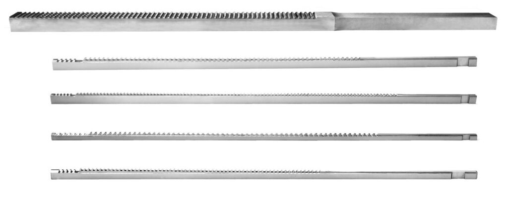
BroachingMach product photo identified on the source Page as keyway broaches. It is representative tooling, not proof of a particular shim sequence, multi-pass configuration, customer job or achieved result.
When May Splitting the Cut Be Justified?
Tool length and machine envelope
A progressive broach needs enough tooth development to distribute the planned stock removal and still provide pilots, finishing teeth and pull or push interfaces. If the resulting tool conflicts with available stroke, daylight, handling or guidance, the engineering team may evaluate a staged set.
Measure the complete working envelope, not only nominal machine stroke. Include loading position, puller engagement, tool change, chip guards, fixture height and safe clearance. Review the available broaching-machine configurations before freezing the tool route.
Cutting load and load distribution
Splitting the material removal may change how many teeth are engaged and how load develops during the cut. That can make a route feasible, but “more passes equals less force” is not a design rule. A later pass can engage more flank area, encounter a distorted first cut or begin with poor guidance.
Calculate each stage from its actual tooth geometry, material condition, engagement and simultaneous cutting edges. The broaching-machine tonnage guide explains the required inputs, but the final tool designer and machine supplier must review the application.
Chip space and evacuation
Each cutting tooth must carry its chip until a reliable exit or evacuation point. A deep feature, long cut or adhesive material can exhaust available gullet capacity before the tool clears. Dividing the route may help only if chips are actually removed between passes and the next tool enters a clean feature.
If chips remain in a keyway, spline space, fixture pocket or bushing, the next pass can recut or pack them. That raises local load and may mark the surface or damage an edge.
Roughing and finishing need different conditions
A separate finishing tool can be useful when the roughing route and final sizing function need different tooth design, guidance or maintenance control. It can also isolate a replaceable finishing stage from a larger roughing asset.
The benefit must be weighed against inter-tool variation and intermediate control. A finishing broach should not be expected to correct an unstable rough feature, a displaced datum or uncontrolled heat-treatment distortion.
Feature geometry or machine architecture
Some profiles, interrupted surfaces or external forms may be easier to approach in defined stages. A multi-station machine can keep each tool and chip path separate, while a single-station route may reduce transfers. Neither layout is universally superior.
For long slender push tools, buckling risk and guidance remain central. For pull tools, confirm pull-end engagement, front and rear guidance and tool handling. See push versus pull broaching for the load-path distinction.
Why a Lower Per-Pass Load Is Not the Whole Decision
Even when calculated load per pass falls, total process risk may rise. The part is loaded more than once, the fixture sees repeated reactions, and an operator or automation system may handle another tool or shim. Every interface has to remain mistake-proof.
Compare complete routes using:
- Peak and changing load for every pass, not an average across passes.
- Machine force, stroke, guidance, speed range and duty requirement.
- Tool length, stiffness, gullet capacity and resharpening strategy.
- Number of loading, cleaning, inspection and transfer events.
- Datum repeatability between tools or stations.
- Reaction plan for a failed intermediate feature.
- Representative cycle study rather than an assumed time saving.
Do not authorize the process because a press can move the first tool. A broach-breakage prevention review should cover alignment, tooth condition, chip packing, workpiece hardness and overload protection for every stage.
Preserve the Datum and Control Cumulative Error
The second tool follows what the first operation actually created, not the nominal CAD model. If the part is unclamped and reloaded, bore runout, face seating, burrs or fixture debris can change the relationship between the cutting path and the design datum.
Choose the locating scheme before dividing the tool. For an internal keyway, the finished or prepared bore may guide the bushing while a face controls axial position. For a spline or irregular form, pilots and fixture locators may establish a different datum chain. The plan should answer:
- Which surfaces locate every pass?
- Does the first cut become a locator for the second tool?
- Can the part stay clamped while tools change?
- What cleaning step is required before reclamping?
- How is angular orientation maintained?
- Which intermediate characteristic predicts a safe final pass?
If one pass drifts, a later tool may follow the drift rather than correct it. Add inspection where it can prevent damage, not merely where it is convenient to collect data.
Plan Cleaning, Cutting Fluid and Tool Identification
Between passes, remove chips without damaging the feature or leaving debris on locators. Confirm that the cutting fluid reaches the active edge and that the chosen fluid is compatible with the material, coating, machine and filtration system. Use the broaching cutting-fluid guide as a starting framework.
Tool and shim identification should be unambiguous. Sequence errors are foreseeable when similar broaches, bushings or shims share a station. Use keyed storage, readable IDs, recipe interlocks or sensors appropriate to the production system. Record the tool condition by pass because one stage may wear faster than another.
Intermediate and Final Inspection
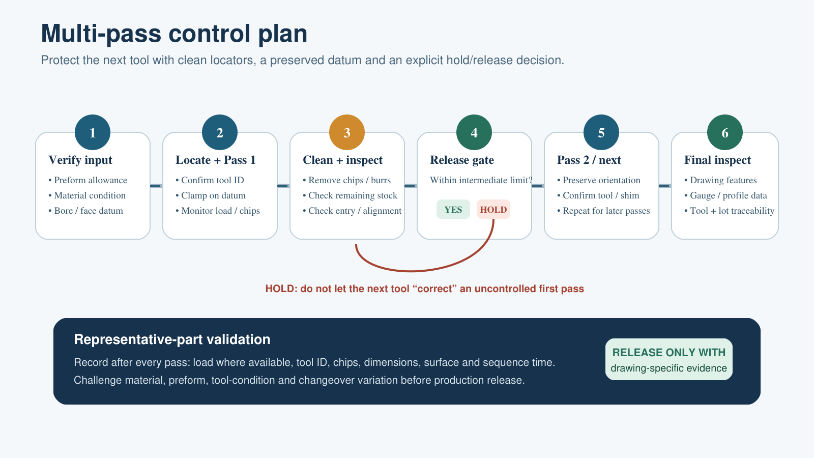
A multi-pass control plan preserves the datum, removes chips and uses intermediate limits to decide whether the next cut may proceed. Final acceptance remains drawing-specific.
Intermediate inspection is not necessarily a full final inspection. It should confirm the characteristics needed to protect the next tool and final part. Depending on the feature, that may include remaining stock, entry condition, orientation, straightness, burrs, chip clearance or evidence of overload.
Final inspection must use the drawing's acceptance method. Width, depth, profile, position, lead, runout, surface condition and gauge response are different characteristics; one go/no-go result may not explain a process shift. Record tool identity, pass sequence, workpiece lot and machine/station so a trend can be traced.
For initial qualification, measure representative parts after each pass. This reveals whether variation originates in the preform, first cut, relocation or finishing stage.
When Is Another Pass the Wrong Answer?
Do not add a pass only to rescue a process that has not been defined. A different solution may be better when:
- The pre-hole, casting or forged preform leaves unstable allowance.
- The current broach has the wrong tooth rise, pitch, guidance or chip capacity.
- The machine lacks rigidity, alignment, stroke or safe tool handling.
- A fixture cannot preserve the required datum through transfers.
- Heat treatment moves the feature after all broaching passes are complete.
- Production volume cannot justify extra handling and control.
- Shaping, keyseating, skiving, milling, grinding, EDM or another method better matches access and volume.
The correct comparison is not “one pass versus two” in isolation. Compare a redesigned single broach, a sequenced tool set, a better preform, another machine architecture and alternative processes against the same drawing and production requirement.
Validate the Route Before Production Release
Use a closed qualification loop:
- Freeze the input. Confirm the part drawing, datum scheme, material specification and condition, preform allowance, feature access, annual and batch quantities, and final inspection method.
- Model each pass. Define the stock removed, engaged teeth, load curve, chip volume, guidance, cutting fluid and remaining condition after every stage.
- Match the equipment. Verify force, stroke, daylight, speed, fixture reaction, tool interfaces, chip handling, controls and safety for the complete sequence.
- Design the control plan. Specify tool IDs, shim order, cleaning, intermediate limits, stop criteria and traceability.
- Run representative parts. Use production material and realistic preforms. Record force or load signals where available, tool condition, dimensions, surface observations and sequence time.
- Challenge the process. Include expected material and preform variation, tool condition and normal changeovers before approving capability.
For a custom application, send the full data package to the broach-tooling design team, not only the final profile.
RFQ Checklist for a Multi-Pass Broaching Review
Provide:
- Finished part and preform drawings with datums and tolerances.
- Workpiece material, hardness range, heat-treatment stage and lot variation.
- Feature type, length of cut, through/blind access and exit condition.
- Current allowance and how it varies around the profile.
- Required surface and inspection method, including available gauges.
- Existing broach, bushing, shim, holder and pull-end details.
- Machine force, stroke, daylight, speed range and interface drawings.
- Fixture concept and whether the part remains clamped between passes.
- Cutting-fluid, filtration and chip-removal system.
- Quantity, takt requirement, automation level and changeover constraints.
- Current failure evidence: load records, dimensions, wear photos and rejected samples.
BroachingMach's broach-tool overview can help identify the relevant tool family, but the final route requires application-specific review.
Preguntas frecuentes
Does a progressive broach count as multi-pass?
Not if it completes the planned feature in one movement through the part. Its roughing, semi-finishing and finishing tooth sections are stages within one pass.
Is a shimmed keyway broach a multi-pass process?
Yes, when the specified procedure uses the broach, then adds a defined shim and passes the tool again to reach the finished depth. Follow the toolmaker's exact bushing and shim sequence.
Does adding a pass always reduce broaching force?
No. It changes the stock and engagement assigned to each stage, but actual peak load also depends on material, tooth geometry, simultaneous engagement, guidance, wear, chips and the condition left by the preceding pass.
Can two passes use the same broach?
They can in a designed guided/shimmed system. Other routes use different roughing and finishing broaches. The process sheet must identify the intended architecture.
Is multi-pass broaching the same as a multi-station machine?
No. A pass is a cutting step; a station is a physical location. Multiple passes may occur at one station, and multiple stations may perform operations that are not repeated passes on the same feature.
How do I decide whether to split the cut?
Compare the complete tool, machine, fixture, chip, datum and inspection plans. Calculate each candidate route, then validate it on representative parts. There is no universal stock, force or tolerance threshold that makes every application multi-pass.


