

Conceptual illustration of a technician inspecting broach teeth. It is not a photograph of a BroachingMach inspection station and does not replace a qualified tool evaluation.
The right time to resharpen a broach tool is before normal edge wear becomes tooth damage, unstable part quality or an overload event. Do not wait for the broach to break, but do not use a universal part count either. Material, hardness, rise per tooth, cutting length, alignment, lubrication and tool geometry can produce very different wear rates.
Use three sources of evidence together:
- The parts: finish, size, burrs, tearing and material pickup.
- The process: cutting load, sound, chip behavior, cycle stability and machine alarms.
- The tool: edge rounding, wear land, chipping, built-up material and gullet condition.
A trend across these sources is stronger than a single symptom. Some conditions, such as a chipped tooth or sudden abnormal force, require an immediate stop and inspection.
The Short Answer
Remove the broach for evaluation when you see a repeatable loss of part quality, a sustained change from the established cutting-load baseline or visible cutting-edge wear approaching the limit defined for that tool. Stop immediately for cracks, chipped teeth, pull-end damage, severe material pickup, sudden force increase or any evidence that the tool is no longer guided or loaded correctly.
The objective is not to use every possible minute of edge life. It is to resharpen while minimum controlled stock removal can restore the cutting geometry and before damage forces a more extensive reconditioning or replacement.
Monitor Three Signal Groups
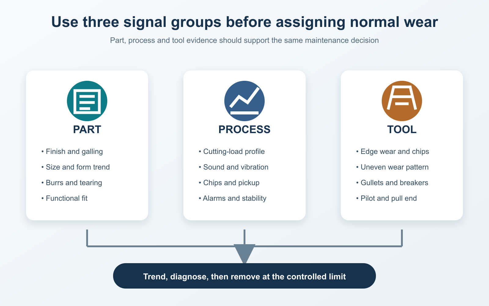
Use part, process and tool evidence together. One symptom can have several causes, so confirm the trend before assigning it to normal wear.
1. Signals From the Workpiece
Watch for changes from the approved first-off and stable-production parts:
- Tearing, scoring or galling
- Deteriorating surface finish
- Burrs that grow beyond the normal condition
- Keyway, spline or form dimensions trending toward a limit
- Taper, drift or angular error
- Material smeared onto the cut surface
- Inconsistent functional gage or mating-part fit
- Local defects that repeat at the same position
Part defects do not prove that the cutting edge is dull. Poor alignment, a dirty fixture, material variation, inadequate lubrication, chip packing or a damaged guide can create similar symptoms. Record where the defect occurs and whether it repeats on consecutive parts.
2. Signals From the Broaching Process
Establish a baseline during a known-good tool condition. Depending on the machine, monitor:
- Pulling force, hydraulic pressure, motor current or axis load
- Peak load and the load profile through the stroke
- New vibration, chatter or unusual sound
- Change in chip shape, color or evacuation
- Material pickup on teeth
- Longer cycle caused by operator intervention or cleaning
- Increased frequency of overload warnings
- Workpiece lifting, movement or difficult tool release
A gradual rise from a stable baseline can support a wear diagnosis. A sudden step change is more likely to require an immediate check for a chipped tooth, material-hardness change, blocked chip space, fixture movement, misalignment or lubrication failure.
Do not reset an alarm or increase machine force merely to finish a batch. That can convert a recoverable edge into broken teeth, a damaged pull end or a scrapped workpiece.
3. Signals From the Tool
Clean the tool safely and inspect under adequate light and magnification. Look for:
- Rounded cutting edges or a consistent wear land
- Small edge chips or microchipping
- One tooth carrying more wear than adjacent teeth
- Built-up material at the cutting edge
- Cracks, impact marks or corrosion
- Damaged chip breakers
- Packed chips or scoring in gullets
- Uneven wear across the tooth width
- Damage to pilots, guides, pull ends or retrieval features
- Coating loss that differs sharply from the normal pattern
Document the tooth number or section where damage appears. Wear concentrated on one side suggests that alignment, support or material entry should be checked in addition to sharpening.
Immediate-Stop Conditions vs Planned Sharpening
| Condition | Response |
|---|---|
| Visible crack, chipped tooth or damaged pull end | Stop; quarantine and obtain a qualified repairability evaluation |
| Sudden abnormal cutting load or new severe noise | Stop; inspect tool, workpiece, fixture, alignment, chips and lubrication |
| Workpiece lifts, tilts or binds | Stop; do not force the stroke or reverse through a trapped part |
| Repeating tears, galling or out-of-tolerance size | Hold parts; verify setup and inspect the cutting edges |
| Gradual load rise with normal setup and material | Schedule removal before the defined stop limit |
| Measured wear reaches the tool-specific limit | Remove for controlled resharpening |
| Stable part, process and tool condition | Continue while recording the trend |
Immediate removal protects both people and equipment. Planned removal protects tool economics: a lightly worn edge may need sharpening, while a tool run beyond its limit may need re-stepping, geometry correction or repair.
Do Not Set the Interval From Part Count Alone
A fixed number of parts can be useful after the process is proven, but it should be an outcome of tool history rather than a borrowed rule.
Tool life changes with:
- Workpiece material, hardness and microstructure
- Amount of stock removed by each tooth
- Total cutting length and interrupted features
- Broaching speed
- Tool material, heat treatment and coating
- Rake, relief, chip breaker and gullet design
- Machine and fixture alignment
- Coolant chemistry, concentration, delivery and filtration
- Chip evacuation and cleaning
- Previous sharpening history
- Handling and storage
Start with conservative inspection intervals. When several tool runs show a repeatable relationship among parts, load and measured wear, convert that evidence into an alert point and a planned change-out point. Revalidate after a material, supplier, heat treatment, coating, tool design or machine change.
A Diagnostic Sequence Before Blaming the Edge
Step 1: Hold the Process State
Record the affected part number, material heat or lot, machine, fixture, program, tool ID, sharpening count, coolant condition and load trace. Preserve the suspect part and chips if they contain useful evidence.
Avoid making several changes at once. If feed, coolant, alignment and tool are changed together, the team cannot learn which factor caused the improvement.
Step 2: Compare With the Baseline
Compare current:
- Critical dimensions and surface condition
- Peak load and load profile
- Chip formation and material pickup
- Tool photographs
- Coolant condition and flow
- Fixture and guide checks
The baseline should come from the same part family and a known-good tool, not from an unrelated broaching operation.
Step 3: Rule Out Process Causes
Check workpiece hardness and pre-bore size, fixture cleanliness, support-face condition, machine alignment, guide condition, tool seating, chip clearance and lubrication. The broaching troubleshooting guide provides a broader symptom-based review.
If pickup or heat changed with coolant condition, review the Guide sur les fluides de coupe pour le brochage. Sharpening a good tool will not correct a blocked nozzle or unsuitable fluid.
Step 4: Inspect the Entire Broach
Do not look only at the first visibly worn tooth. Compare roughing, semi-finishing and finishing sections, tooth-to-tooth rise, chip breakers, gullets, pilots and pull features. A qualified tool shop should decide how much stock to remove and whether normal sharpening is sufficient.
Step 5: Make the Maintenance Decision
Use the tool drawing, current measurements, damage pattern and sharpening history to choose sharpening, reconditioning, repair or replacement.
Sharpening, Reconditioning, Repair or Replacement?
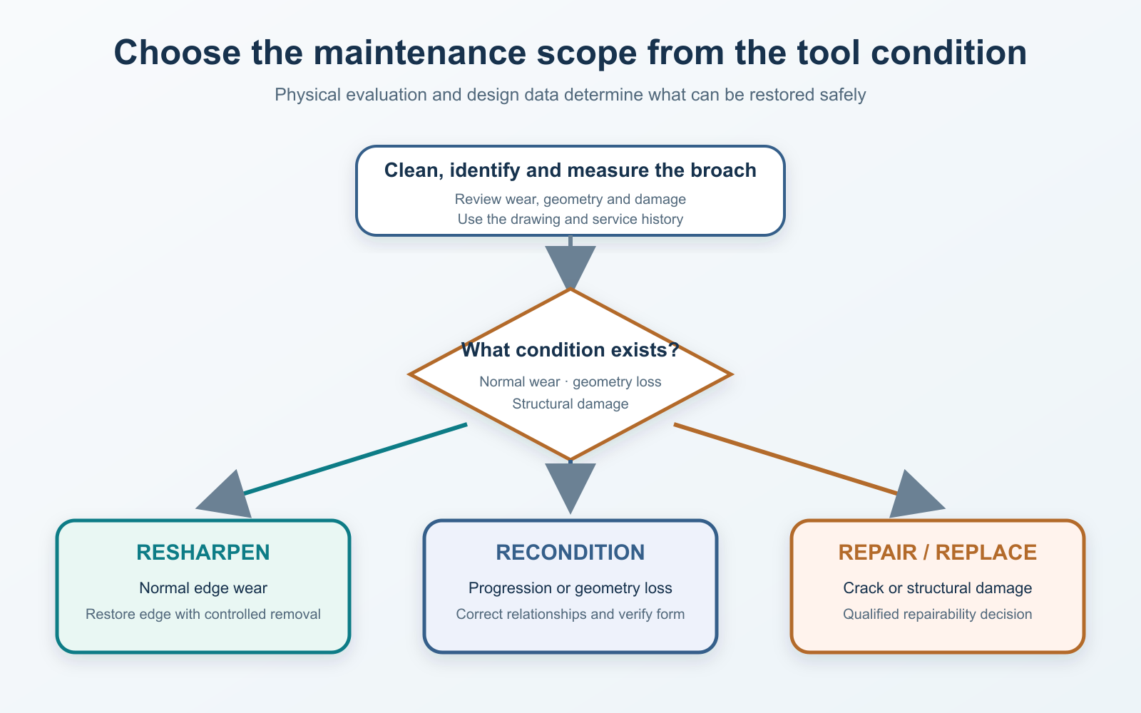
Normal edge wear may need sharpening. Geometry loss or uneven tooth condition may need reconditioning. Cracks and structural damage require a repairability decision.
Resharpening
Resharpening restores the cutting edge through controlled grinding while preserving the intended tooth relationship and geometry. It is the likely path when wear is normal, damage is limited and enough usable geometry remains.
Removing more material than necessary consumes tool life and can alter form size or tooth strength. The grinding method, wheel, coolant, setup and inspection must suit the broach design.
Reconditioning
Reconditioning is broader than sharpening. It may include re-stepping tooth sizes, correcting clearance or rake relationships, restoring chip breakers, recoating and dimensional verification. It becomes relevant after multiple sharpenings, uneven wear or geometry drift.
BroachingMach's broach reconditioning service describes the commercial inspection, cleaning, sharpening, coating and final-examination pathway. This article does not determine whether a particular tool is repairable; that requires a physical evaluation and the original design information where available.
Repair or Replacement
Chipped teeth, cracks, bent sections, damaged pull ends, severe corrosion or lost geometry may require specialized repair or make replacement safer and more economical. Do not assume a weld, hand grind or local touch-up will preserve strength, pitch, rise per tooth and profile.
The guide to avoiding broach breakage covers overload, alignment, handling and maintenance factors that should be corrected before a repaired or new tool returns to production.
Why Incorrect Sharpening Can Shorten Tool Life
A broach is a coordinated sequence of cutting teeth. Sharpening one tooth without respecting pitch, rise, rake, relief and the next tooth's load can transfer excess stock removal downstream.
Common risks include:
- Uneven stock removal from tooth to tooth
- Altered rake or clearance
- Loss of chip-breaker geometry
- A groove or step that traps chips
- Excess removal from finishing teeth
- Form-size change after grinding
- Heat damage from the grinding process
- Inadequate inspection after sharpening
For this reason, do not treat a long broach like a general shop blade. Use the tool drawing and a specialist capable of measuring and restoring the required geometry.
Build a Tool History Record
Assign every production broach a unique ID. Record:
| Field | Purpose |
|---|---|
| Tool ID and drawing revision | Connects the physical tool to design requirements |
| Part family and material | Separates different wear environments |
| Machine, fixture and guide | Identifies setup-dependent patterns |
| New or service date | Establishes the maintenance timeline |
| Parts or cutting length | Provides exposure data |
| Load baseline and trend | Detects gradual or sudden change |
| Part-quality trend | Links edge condition to the output |
| Inspection findings | Identifies tooth and section affected |
| Sharpening/reconditioning count | Tracks consumed geometry |
| Removal reason | Preventive, quality, load, damage or failure |
| Service report and measurements | Preserves what was changed |
The history helps choose a safe inspection interval, compare tool vendors or coatings and distinguish systematic setup damage from expected wear.
What to Send With the Tool for Evaluation
Provide more than the instruction “regrind.”
- Tool ID, drawing and original manufacturer if known
- Part drawing and profile tolerance
- Material and hardness
- Current form size or quality problem
- Description and location of tearing, galling or dimensional change
- Machine load before and after the problem
- Photographs of the tool, parts and chips
- Number of previous sharpenings or service reports
- Machine, fixture, guide and coolant details
- Any impact, overload, jam or handling incident
- Required return condition and inspection documentation
For internal forms, state the relevant size limits. For external forms, state the applicable upper and lower requirements. The evaluator needs the intended finished geometry, not only the worn tool.

BroachingMach photo of round and spline broaches. Different tooth sections, profiles and service histories require tool-specific inspection rather than one universal sharpening interval.
Return-to-Service Checks
Before production:
- Review the service report and confirm tool identity.
- Verify critical dimensions, tooth condition and protective coating or oil.
- Inspect pull end, pilot, guides and chip spaces.
- Clean the machine, fixture and support surfaces.
- Confirm alignment, tool orientation, stroke limits and lubrication.
- Run a controlled first-off part.
- Record the new load trace and compare it with the known-good baseline.
- Inspect the first-off part and functional fit.
- Increase monitoring during the initial production run.
A sharper tool does not make an incorrect setup safe. Return-to-service validation should prove the tool and the process together.
Foire aux questions
How many parts can a broach cut before sharpening?
There is no reliable universal number. Use tool history for the specific material, geometry, machine, fixture and lubrication. Part count becomes useful only after repeated runs correlate it with load, quality and measured wear.
Does higher cutting force always mean the broach is dull?
No. Harder material, excess stock, misalignment, chip packing, workpiece movement, coolant failure or a damaged tooth can also raise force. A sudden increase deserves an immediate process check.
Can a chipped broach tooth be sharpened out?
Possibly, but only a qualified evaluation can determine repairability. The result depends on damage depth, tooth location, remaining geometry and how restoring that tooth changes the load on following teeth.
Is broach sharpening the same as reconditioning?
No. Sharpening restores cutting edges. Reconditioning may also correct tooth progression, clearance, chip breakers, form size, coating and other geometry after repeated service or uneven wear.
Should broaches be sharpened in-house?
Only when the shop has the correct machine, measurement capability, tool drawings and broach-grinding expertise. Convenience does not justify risking tooth geometry or tool strength.
Use Trends to Remove the Tool Before Damage
The best sharpening point is a controlled maintenance decision based on part quality, process trend and physical inspection. Set alert and stop limits from the tool's real history, investigate sudden changes and keep sharpening separate from broader reconditioning or repair decisions.
For tooling fundamentals, see the complete guide to broaches and Guide de conception des broches. For a tool-specific evaluation, review BroachingMach's broach tools or contact the engineering team with the drawing, material, service history and observed symptoms.


