
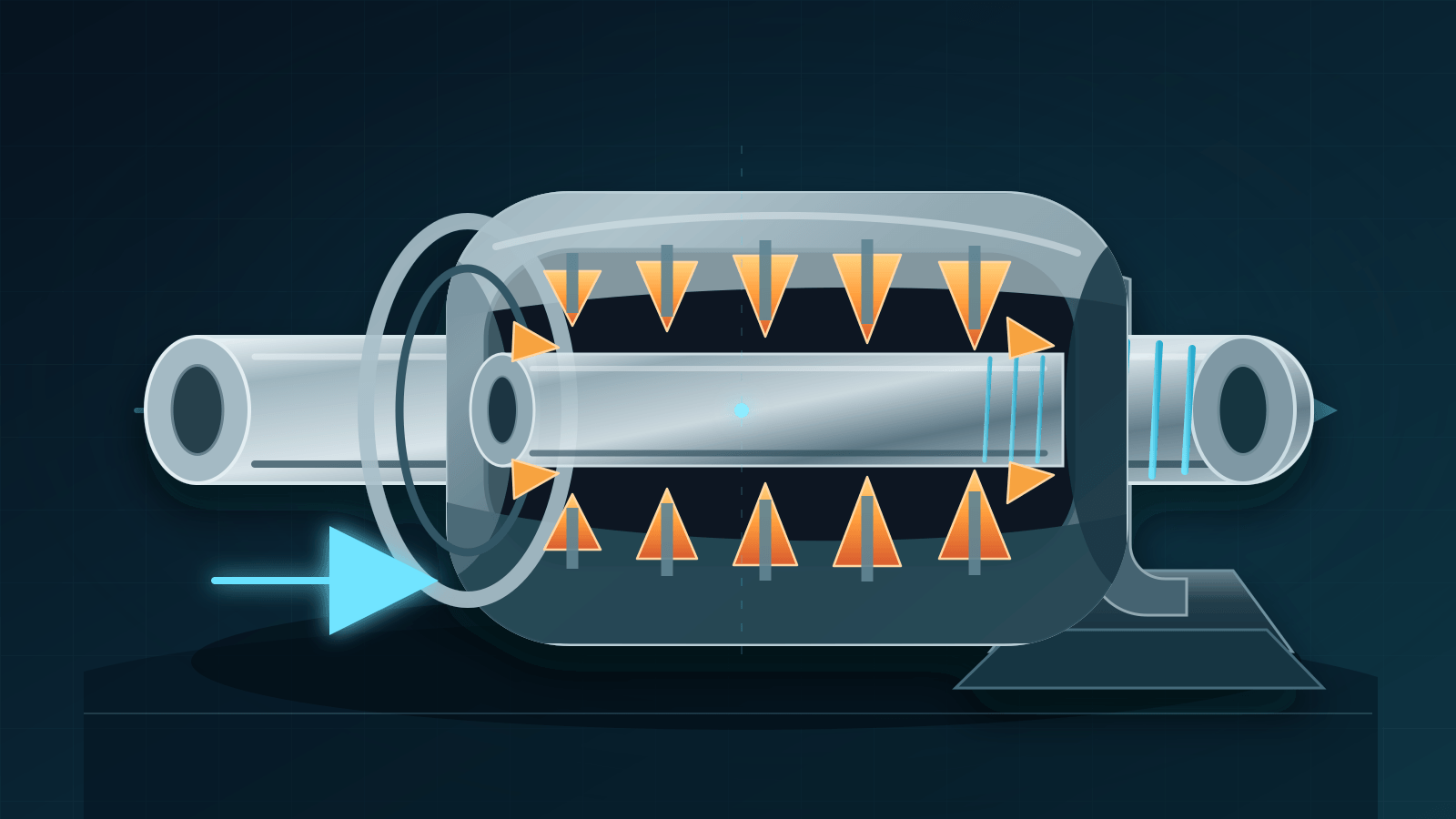
Conceptual illustration of a cylindrical workpiece passing through a pot-broach assembly. It is not a dimensional tool drawing, a customer project or a photograph of BroachingMach equipment.
Pot broaching is an external broaching method in which cutters are arranged around the inside of a pot-like holder. A cylindrical or generally round workpiece passes axially through that cutting envelope—or the tool assembly moves over the supported part—so progressively sized cutting edges generate an external spline, gear-like form, serration, slot pattern or other suitable profile.
The method can cut many features around the circumference in one controlled traversal, but it is not automatically the best process for every external form. The workpiece must enter and leave the cutting envelope, the blank and fixture must carry the broaching load, and the machine must provide the required force, stroke, alignment, speed and chip control.
This guide explains the process, tooling, application gates, machine requirements, inspection plan and alternatives to compare before requesting a pot-broaching system.
How Pot Broaching Works
A pot broach reverses the visual arrangement of a familiar internal pull broach. With an internal broach, cutting teeth are on the outside of a long tool that passes through a starting hole. With a pot broach, multiple cutting elements face inward around a holder, and the outside of the workpiece passes through their central opening.
The relative motion may be produced in more than one way:
- The pot assembly remains stationary while the machine pushes or pulls the workpiece through it.
- The workpiece remains supported while the machine moves the pot assembly over it.
- A machine may divide the operation between more than one tool or station.
The selected arrangement changes loading height, fixture design, tool handling, chip fall, machine stroke and automation. “Pot broaching” defines the cutting concept, not one universal machine layout.
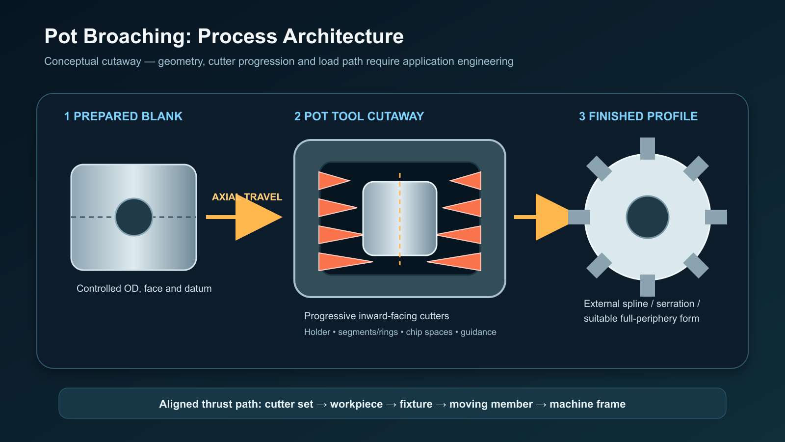
Conceptual cutaway of a pot-broaching process. Cutter layout, tooth progression, chip space, guidance and direction of motion must be engineered for the actual profile and blank.
As the part advances, cutting edges progressively remove stock. Later edges size or finish the form according to the tool design. The machine and fixture must keep the workpiece axis, tool center and load path aligned while resisting any tendency for the part to turn or deflect.
Pot Broaching Is Not Rotary Broaching
The word “pot” describes the holder and surrounding cutter arrangement. It does not mean the wobble action used in rotary broaching.
| Method | Typical cutting relationship | Common use |
|---|---|---|
| Pot broaching | Workpiece passes through surrounding progressive cutters, or the pot moves over the part | External full-periphery splines, gear-like forms, serrations and suitable special forms |
| Internal linear broaching | Progressive external teeth on a long broach pass through a starting hole | Internal splines, keyways, rounds and other through profiles |
| Surface broaching | A flat or contoured broach moves across an accessible surface | Flats, slots, shoulders and open external forms |
| Rotary broaching | An angled, freely rotating or driven tool generates a polygon/profile through a wobble action | Selected internal or external polygons and forms on lathes or mills |
The external broaching guide 以及 surface broaching guide provide the broader process context. Pot broaching is one specialized external route within that larger family.
How Is a Pot Broach Built?
Public manufacturer descriptions show more than one construction style. Some refer to stick-type cutting elements mounted around a holder; others refer to ring-type elements. A production tool may divide roughing, semi-finishing and finishing work across segments, rings or stations.
The supplier must define:
- Cutter or ring arrangement
- Tooth progression and stock distribution
- Tool material, heat treatment and coating
- Guidance and concentricity features
- Chip space and chip-removal path
- Coolant or lubrication delivery
- Assembly, indexing and replacement method
- Sharpening and size-restoration strategy
- Safe lifting, storage and changeover
Do not assume that one worn element can simply be replaced without affecting the set. The toolmaker should explain how elements are matched, located, measured and restored as an assembly.
The starting point is a complete broach-tooling design review, not a catalog diameter. Profile data, blank stock, material condition, machine load, fixture and inspection method are interdependent.
First Gate: Can the Part Pass Through the Tool?
Pot broaching normally requires a clear axial path for the workpiece and its finished external profile. Before discussing machine force, check the geometry:
- Can the target area enter and exit the tool without another flange, shoulder or feature colliding?
- Is the feature parallel to the direction of travel?
- Is there adequate lead-in and runout for progressive cutting?
- Can the fixture support the part without occupying the tool path?
- Will chips have space to form and leave?
- Does a thin wall, interrupted cut or asymmetric blank create unacceptable deflection or torque?
- If the profile is helical, indexed or phased to another feature, what synchronized motion and datum control are required?
A blocked tool path is a process-selection problem, not a larger-machine problem. Hobbing, shaping, skiving, milling, rolling, grinding or a different broaching arrangement may be more suitable when the part cannot traverse the pot.
Define the External Form and Blank
“External spline” is not enough information for tooling. Supply the governing drawing or digital definition, including:
- Profile standard and revision, if applicable
- Tooth count, module or diametral pitch, pressure angle and fit
- Major, minor and form diameters
- Tooth thickness or space width and measurement method
- Profile, lead, runout and concentricity requirements
- Chamfers, radii, reliefs and adjacent shoulders
- Datum references and angular phasing
- Material specification and heat-treatment condition
- Coating, plating or later finishing allowances
The blank must also be controlled. Variation in pre-turn diameter, runout, scale, hardness or stock distribution changes cutting load and finished geometry. The application review should define which features are prepared before broaching and which operations follow it.
For spline terminology and inspection context, see the spline broaching guide. Do not copy an internal-spline tool concept directly into an external pot-broach application.
Force, Stroke and the Structural Load Path
The cutting force changes as teeth engage, stock varies and different sections of the tool work. A supplier should estimate or test force over the complete stroke rather than quote only a machine nameplate.
The load path runs through:
- The cutting edges and pot holder
- The workpiece
- The locating and support fixture
- The moving table, ram or pull mechanism
- The machine frame and foundation
Misalignment can create side load, uneven tooth engagement, profile error, premature wear or tool damage. An asymmetric external form may also create torque that the fixture must resist without losing the specified angular relationship.
Use the site's broaching-machine tonnage guide as a starting framework, but require the tool and machine suppliers to validate the real application. No universal force per tooth or safety factor applies to every profile, material and tool construction.
Machine and Automation Requirements
The broaching-machine overview can help identify candidate platforms, but a pot-broaching specification should address the complete cell:
- Rated force over the required cutting-speed range
- Cutting, return and clearance strokes
- Tool and workpiece envelope
- Vertical, horizontal or special orientation
- Push, pull or moving-pot arrangement
- Table, ram and fixture guidance
- Part loading and unloading
- Tool loading, lifting and protected storage
- Chip and coolant collection
- Guarding, interlocks and safe maintenance support
- Load, position and cycle monitoring
- Manual, robot or line integration
- First-piece and in-process inspection
Multiple stations may be used when the process is split across tools, when more than one operation is required or when production handling supports it. A multi-station layout is not inherently superior; compare load/unload time, tool cost, floor space, traceability and recovery after a tool or machine fault.
Fixture, Datum and Anti-Rotation Control
The fixture must locate the blank from datums that make sense for the finished part. It must support the broaching thrust without distorting the workpiece or obscuring the tool path.
Ask:
- Which diameter, face or center establishes the tool axis?
- How is angular phase established relative to a keyway, hole or existing tooth?
- Where does the broaching force react?
- What prevents the part from rotating?
- How is a misloaded or wrong blank detected?
- How are chips kept away from locating surfaces?
- Can the operator or robot load the part without contacting cutting edges?
The process plan should also control part orientation between previous machining, broaching, heat treatment and final inspection. A capable cutting tool cannot recover a lost datum relationship.
Chips, Cutting Fluid and Tool Condition
Pot tooling encloses the cutting zone around the workpiece, so chip space and evacuation deserve explicit review. Chips trapped between a cutter and the new profile can mark the part, overload an edge or prevent full seating.
Cutting-fluid selection depends on workpiece material, tool material/coating, speed, heat, finish and the machine's delivery and filtration system. The cutting-fluid guide explains the broader decision. The toolmaker should identify delivery points and confirm whether chips fall, flush or require mechanical removal in the selected orientation.
Monitor more than finished size:
- Machine load or force trend
- Part surface and burr pattern
- Tooth wear, chipping and built-up edge
- Chip shape and color
- Coolant flow, concentration and cleanliness
- Profile, lead, runout and tooth-thickness trend
Define stop and escalation rules before production. Do not wait for a broken cutter or rejected batch to trigger inspection.
Inspection and Acceptance Plan
The inspection plan must match the functional requirement. Depending on the profile, it may include:
- Major and minor diameters
- Tooth thickness, space width or measurement over pins
- Profile and lead
- Runout and concentricity to a datum
- Angular phase
- Surface condition and burrs
- Functional gaging or mating-part check
Agree on blank inspection, first-piece approval, sampling frequency, gage calibration and reaction plan. If the process uses more than one pot, ring or station, define what is checked between stages and how cumulative error is controlled.
Machine acceptance should use representative material, a production-intent blank, the intended fixture and an agreed tool condition. A demonstration on an easier sample does not validate the actual application.
Pot Broaching Compared With Alternatives
| Process | Why it may be considered | Questions to resolve |
|---|---|---|
| Pot broaching | Many external features cut in a controlled traversal | Clear axial path, dedicated tooling, force, alignment and production justification |
| Hobbing | Flexible external gear generation | Required profile, machine availability, cycle and downstream finishing |
| Gear shaping | Internal or external gears and shoulder access | Cutter clearance, productivity and accuracy route |
| Power skiving | Flexible gear/spline generation on suitable CNC equipment | Machine synchronization, tool access and process maturity |
| Rolling/forming | Chipless production for suitable materials and forms | Material flow, blank design, residual stress and tool load |
| Milling | Flexible prototypes, families and accessible features | Cycle, tool access, indexing and finish |
| Rotary broaching | Selected polygons or profiles on lathes/mills | Form limits, depth, holder setup and required quality |
The decision should use the same drawing, volume, quality plan and lifecycle assumptions for every candidate. Do not select pot broaching solely because it can be fast in another application.
Pot Broaching Application Workflow
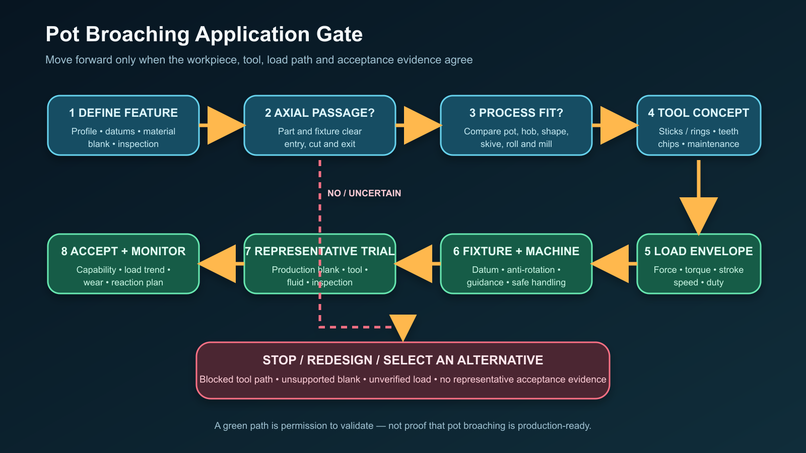
Engineering workflow for deciding whether to quote a pot-broaching route. Every green gate still requires supplier validation, tryout and acceptance evidence.
- Freeze the feature. Define the external profile, datums, material condition and inspection method.
- Check axial passage. Confirm the part, finished profile and fixture can traverse the tool.
- Select candidate processes. Compare pot broaching with generation, cutting and forming alternatives.
- Develop the tool concept. Define sticks/rings, progression, chip space, guidance and maintenance.
- Calculate the real load envelope. Review force over stroke, torque, speed and duty cycle.
- Design the fixture and machine interface. Align the tool, part and structural load path.
- Run representative trials. Use production-intent blanks, tooling, fluid and inspection.
- Accept and monitor. Establish capability, trend variables, maintenance triggers and reaction rules.
BroachingMach Capability Boundary
BroachingMach publishes external and surface-broaching equipment, but the current public inventory reviewed for this article does not establish a dedicated pot-broaching machine or pot-broach product. Do not infer pot-broaching capability from a general external-broaching image.

BroachingMach CNC Hydraulic External Tenon Broaching Machine, shown as a real example of a different external-profile broaching platform. It is not a pot-broaching machine and does not prove suitability for external splines or pot tooling.
The published CNC 液壓外榫拉削機 is described for dovetail-slot disc machining. A pot-broaching inquiry must be reviewed independently from the workpiece drawing, tool concept and production requirement.
If internal capacity is not justified or process knowledge is unavailable, validated production broaching may be compared with buying equipment. Confirm that the supplier has the exact pot-tooling and inspection capability rather than assuming any broaching service can perform the work.
RFQ Checklist
Send the following information:
- Part drawing and 3D model
- External profile standard and inspection definition
- Material, hardness and heat-treatment route
- Blank dimensions, stock allowance and prior-operation capability
- Annual demand, batch size, shifts and target output
- Current process and known quality problems
- Required datum relationships and angular phase
- Available floor space, utilities and loading method
- Preferred automation and traceability
- Tool-change, sharpening and spare-tool strategy
- Factory and site acceptance criteria
- Representative sample parts or blanks
The supplier should return a documented process route, tool concept, force/stroke review, fixture concept, machine scope, inspection plan and acceptance proposal.
常見問題
What does a pot broach cut?
Pot broaches are used for suitable external full-periphery forms such as splines, gear-like teeth, serrations, slots and special profiles on workpieces that can pass through the cutting envelope.
Does the pot tool rotate?
Not in the way a rotary or wobble broach works. Standard pot broaching uses axial relative motion between the workpiece and surrounding cutters. A special helical or indexed application may require additional synchronized motion, which must be engineered separately.
Is pot broaching always completed in one pass?
Many pot applications are designed for one traversal, but complex stock removal, tool limits, quality requirements or machine layout may lead to multiple tools or stations. The actual route must be designed from the part.
Is a vertical machine required?
No universal orientation is required by the process name. Vertical layouts are common in published equipment, but horizontal or special arrangements may be possible. Choose from load path, tool handling, chips, floor space and automation.
Can pot broaching make a blind external feature?
The part and finished profile normally need a clear entry and exit path through the tool. A shoulder or obstruction can make conventional pot broaching impractical. Review the complete geometry before selecting the process.
How is pot-broaching force calculated?
Force depends on the engaged cutting edges, stock per edge, profile length, material condition, tool geometry, friction and process layout. Use a preliminary calculation only for screening and require the tool/machine supplier to validate force over the stroke.
What information is most important for a quotation?
The profile definition, blank and material condition, datums, stock allowance, production schedule, inspection method, axial clearance and representative samples are essential. Without them, a supplier cannot responsibly size the tool, fixture and machine.


