
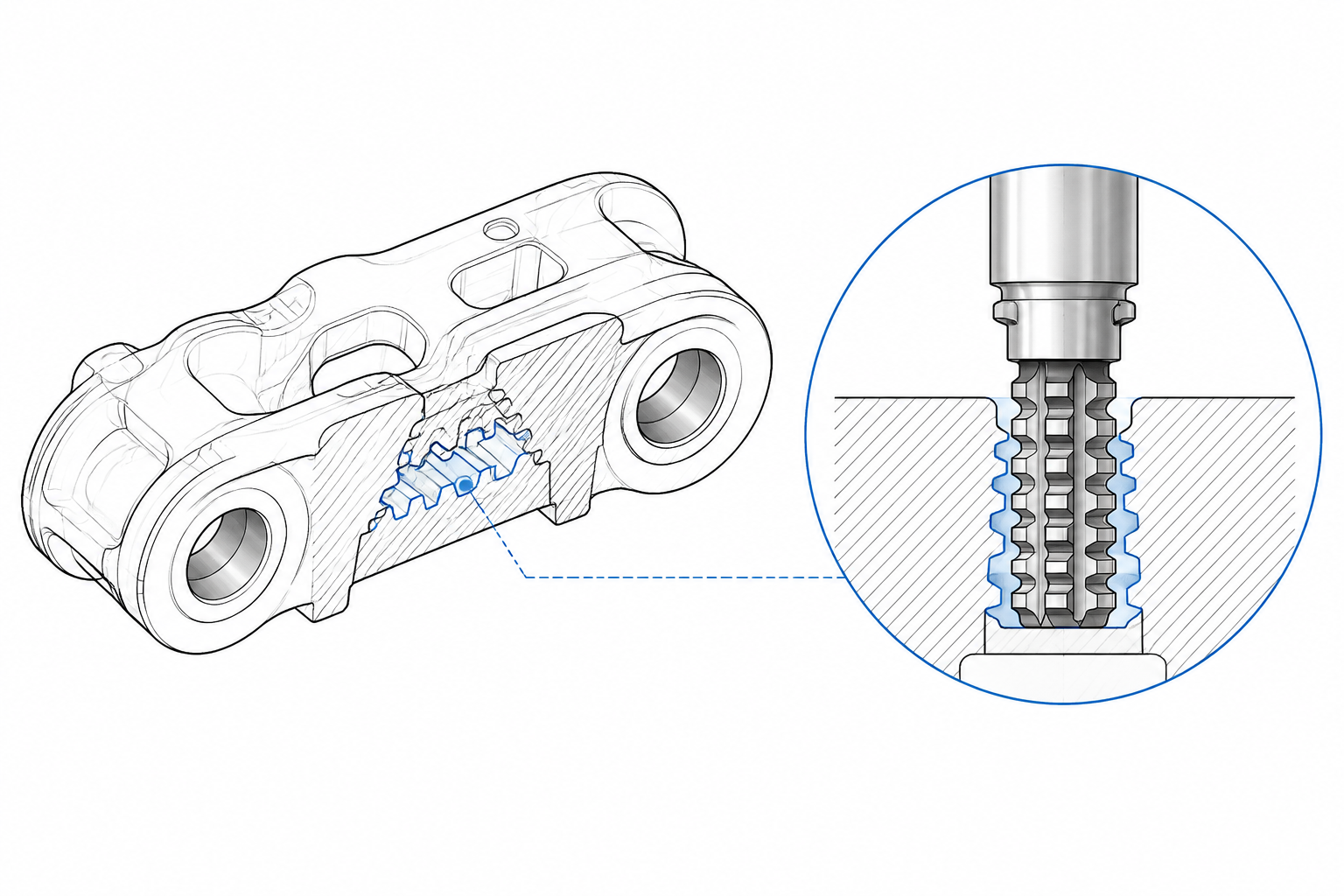
A crawler undercarriage earns its living in the dirt. Between the sprocket that drives it and the ground it pulls over, every component in the track chain carries a share of the drawbar load — and none carries it longer, part after part, than the chain rail link. This forged steel component is the building block of the track: left- and right-hand links are paired, joined end to end by pins passing through bushings, until the chain closes around the undercarriage. The track shoe bolts across the top of the links, the rollers ride on the link rails, and the sprocket teeth engage the link pitch to convert hydraulic power into traction. For earthmoving and agricultural machines the chain is a consumable, replaced in volume for the life of the fleet.
This site already maps the whole manufacturing route: our article on the chain rail link production process walks the complete sequence from forged blank through datum preparation, bores, heat treatment and finishing, with the drawing governing every decision. The present article stays inside one station of that route. It looks at the link the way a broaching application engineer does: which features are realistic broaching candidates and which are not, what the sprocket engagement profile demands of a broach, how forged and heat-treated steel changes the cutting problem, and how fixtures and machine architecture turn a single cut into a takt-rated production step. Where the earlier article manages the process, this one lives at the machine.
What a Chain Rail Link Asks of a Broaching Machine
A chain rail link — called a track link or track chain link interchangeably across the industry, all three names for the same workpiece — concentrates a remarkable amount of engineering into one forging. Around its body sit the functional surfaces that define the undercarriage: pin and bushing bores at each end that set the track pitch, the engagement surfaces that mesh with the sprocket, the machined faces and bolt holes that carry the track shoe, and the rails on which the idlers, rollers and machine weight ride. Each has its own tolerance, datum scheme and finishing process.
The material is where the machining story begins. Links are die forgings in medium-carbon manganese steel of the 40Mn class and its alloyed variants, chosen for the fatigue strength a load-carrying articulated joint needs. Working surfaces are typically induction hardened after rough machining, which means the part arrives at any late-stage operation with hardness gradients, some scale and decarburized skin from forging, and distortion from heat treatment already in the geometry. Volume is the other defining condition: links are made by the tens of thousands on lines balanced to a takt of seconds per part, so any process on that line must cut a defined feature in one repeated pass. Those conditions — complex external profiles, hardened surfaces, forged blanks, relentless volume — are the territory where broaching and the competing processes divide the work.
Broaching Candidates on Forged Track Links
Not everything on a link should touch a broach, and pretending otherwise wastes tooling budget. The candidate list below follows the same rule our production-process article applies to the whole route: the customer drawing, not the machine catalog, decides. A feature belongs on a broaching machine when the cutting path is open and straight, the stock is controlled, the part can be supported close to the cut, and the volume amortizes part-specific tooling. On a link family, that filter sorts the features like this:
| Link feature | Broaching role | Why |
|---|---|---|
| Sprocket engagement profile | Primary candidate | Open straight passage, complex cross section, form consistency drives mesh quality |
| Track shoe mounting faces and bolt seats | Candidate | Open flat or shallow-contoured surfaces; pads and spot faces finish in one stroke |
| Locating features for downstream operations | Candidate | Datum-critical flatness and position produced repeatably per stroke |
| Pin and bushing bores | Not a candidate | Deep internal bores with roundness and position requirements — boring, reaming and honing territory |
| Rail (roller contact) surfaces | Not a candidate | Induction hardened to rolling-contact hardness; finished by grinding |
| Track shoe bolt holes | Not a candidate | Drilled and tapped on transfer or machining-center lines |
Two boundaries are where process plans most often go wrong. The pin and bushing bores are the pitch-defining features of the entire track chain; they are sized, located and finished by boring, reaming and often honing, and no responsible process plan routes them through a broach. The rail surfaces are induction hardened to a level that leaves them economic only for abrasive finishing. Broaching’s claim on the link is the external formed geometry — the engagement profile that meshes with the sprocket, and the open mounting and locating faces around it — subject to the drawing confirming geometry, stock, hardness at the cutting stage and volume.
Broaching the Sprocket Engagement Profile
The engagement profile is the reason surface broaching exists on link lines. The surfaces that mesh with the sprocket teeth wrap a section of complex curvature — flanks, roots and clearance pockets that clear the tooth on one side and transmit drive on the other — directly in bushingless agricultural chains, through the bushing in sealed track chains — along an open, straight path across the link body. A surface broach carrying the female form of that section in progressive cutting teeth removes the forging stock and finishes the profile in one pass. Every link that follows is cut by the same finishing teeth, so the profile on piece ten thousand is the profile on piece one, ground into the tool rather than accumulated from machine motions.
That structural consistency is not a convenience; it is the engineering argument for the process. A track chain meshes with the sprocket through several teeth at once, and the chain is dozens of links in series, so profile error does not stay on the part where it was cut — it sums around the circuit. A link whose engagement pockets deviate from pitch or form produces mesh interference, impact loading, noise and uneven contact pressure, and contact concentrated on a small flank area wears into pitch elongation that eventually skips teeth under load. One deviant link punishes every other link in the chain. The broach’s copy-the-tool character is the direct answer: form and pitch consistency come from one hardened, inspected cutter rather than from stacking indexing errors and setup variation.
The competing route for the same profile is form milling or profiling with per-tooth indexing, and it does have a place — at low volumes, for geometry in flux, or where stock variation argues for a process that adapts per piece. But indexing accumulates position error tooth by tooth, cycle time scales with tooth count, and profile consistency becomes a machine-condition problem instead of a tool problem. At undercarriage volumes, the broach finishes the whole profile in seconds and holds it for the tool’s life. One geometry note applies either way: the engagement profile derives its position from the pin-bore center distance, so whichever process cuts it must locate from the finished bores, which is the subject of the fixture section below.
Interrupted Cuts, Forging Skin and Heat-Treatment State
Broaching a forging is not broaching a machined blank, and the difference shows up in the cut. The link arrives with forging scale, a decarburized skin, draft-angle faces that meet the machined geometry at changing stock depths, and local hard spots from forming and heat treatment. As the broach teeth enter and exit these zones, the chip load per tooth swings rather than holding steady; tooth engagement is interrupted at section changes and the cutting force traces a series of steps instead of a smooth ramp. An engagement profile with its alternating pockets and lands is, by geometry, an interrupted cut even on a clean blank.
What that demands is mostly discipline upstream of the machine. Stock surveys on production-intent blanks — not first articles, but the distribution across a real lot — tell the tool designer how much variation the roughing teeth must absorb and where the semi-finishing section needs length to even out the load before the finishing teeth set the form. The heat-treatment sequence decides the material state at the cut: links broached before hardening cut in a machinable condition and carry the profile through subsequent distortion, while a hardened condition pushes the operation toward the controlled correction role described in the next section. On the machine side, interrupted cutting argues for rigid guidance and a watched force signature — the stroke’s force trace is the earliest warning that skin conditions, stock or tooth wear are drifting out of the validated window.
Tooling Strategy for Medium-Carbon Forging Steel
Link tooling strategy starts from the timing question that governs every heat-treated part: cut soft, cut hard, or split the work. The framework in our hard broaching vs soft broaching comparison applies directly. The usual link arrangement puts the heavy profile-generating work before hardening: high-speed-steel or coated broaches with an aggressive roughing section carry the forging stock out, a semi-finishing section cleans up the interrupted load, and a short finishing section calibrates the form. Medium-carbon steel in the soft condition is well within conventional broach capability; the hard part of the operation is the variability around the cut — skin, local hardness and stock scatter — which the tooth layout must be designed to absorb.
When the process needs to cut or correct after hardening — for instance, to restore a profile that heat treatment has pulled, or to finish a surface hardened deliberately early — the operation becomes hard broaching: a small, controlled allowance taken by carbide-toothed tooling on a rigid machine, with edge geometry and coating selected for the hardened condition. It is a finishing and recalibration step, never the stock-removal workhorse, and it earns its place when it prevents scrap or replaces a slower finishing process. The distinction is material-driven, not label-driven: the tool supplier needs the actual hardness distribution at the cutting stage, not the word “hardened” on a route sheet.
For perspective, the wear problem on link steel is comparatively tame. The same machine family cuts aerospace alloys where chemical wear, work hardening and heat at the edge dominate tool life — the demands of broaching titanium and superalloys make forged manganese steel look straightforward. What link production trades for that friendlier metallurgy is volume and variability: the tool must survive hundreds of thousands of strokes against abrasive skin, so tool life is managed by force trend, dimensional drift and inspected tooth wear, with regrind cycles planned on evidence rather than on failure.
Fixtures: Pin-Bore Datums, Handed Pairs and Multi-Part Loading
Every dimensioned feature on a link traces back to the pin bores: track pitch is the pin-bore center distance, the engagement profile is located from it, and the shoe faces and bolt pattern relate to it. So the broaching fixture locates from the finished bores — hard locating pins in two bores, plus a faced end or pad controlling rotation and seat — and everything the broach cuts inherits that datum chain. The corollary is a condition check every shift: bores with burrs, chips or distortion seated on nominally correct locators still shift the part, and a profile cut on a shifted seat passes the broach and fails the assembly. The general principles are the stock-in-trade of our broaching fixture design guide; the link adds two particular twists.
The first twist is handedness. Links are left- and right-hand parts used in mirror pairs, and the engagement geometry mirrors with them. A line either runs convertible fixtures — locating pins, side rails and stops arranged to flip for the opposite hand, with the change parts positively identified after conversion — or dedicates twin stations, one per hand, fed from the same broach set where the geometry allows. The choice follows changeover frequency and batch size; the non-negotiable is conversion discipline, because a right-hand fixture quietly cutting left-hand parts produces scrap that surfaces only at track assembly.
The second twist is multi-part loading. A single link stroke may take only seconds of cutting, and no takt-balanced line can afford a machine that idles through load and return. Link fixtures therefore carry the part in rows — two, three or four links clamped in one fixture body, all cut in one stroke — so cutting time is amortized across the nest and the cycle per link collapses. The fixture grows into a pallet-sized workholder with automated clamping, seated close to the cut path so the interrupted cutting reaction passes into the machine base instead of through the part. Chip evacuation deserves explicit attention at this density: packed chip space is a broach-breakage mechanism, not a housekeeping issue.
Machine Architecture and Line Takt
Link broaching lives on the surface side of the machine families surveyed in our broaching machines overview — external, open geometry, straight-line cutting path. Within that family, architecture is driven less by the cut than by the part: links are dense forgings handled at volume, so workpiece flow, loading height and stroke access weigh as heavily as force and travel. Horizontal surface machines suit pass-through lines where the nest indexes through the station; vertical machines suit heavy nests loaded from overhead handling. Either way, sizing comes from the application numbers — stock and width on the engagement section, teeth engaged simultaneously, cutting speed for the material condition, and the resulting force curve compared with rated capability across the full stroke, not at a catalog peak.
Takt is where the machine earns or loses its place. The per-link time is the full cycle — load the nest, clamp, stroke, return, unclamp, unload — divided by the nest quantity, and a broaching station competes against the line rate with three levers: nest density, return-stroke strategy (rapid return, or twin shuttles that exchange nests while one cuts) and integrated handling that keeps operator time out of the critical path. Because the engagement profile is cut in one pass, adding links to the nest costs stroke time only marginally — the tooling section is already engaged — which is why nested loading, not faster cutting, is usually the shortest route from a slow station to a balanced one. The same force monitoring that watches tool condition doubles as takt insurance: an abnormal-force stop mid-stroke is a line event, and recovery should be a reposition and restart, not a tool extraction.
The Chain Rail Link Broaching Machine
The machine built around this application is the chain rail link broaching machine, a member of our surface broaching machine family configured for forged undercarriage work. What defines it is less a catalog attribute than the engineering package around the cut: the broach set ground for the engagement profile and mounting faces of your link family, the pin-bore-datum fixture with its handed conversion parts or twin stations, the nest and clamping scheme sized to your takt, and the force and tool-life monitoring that keeps a high-volume station inside its validated window. We quote link applications that way — machine, tooling, fixture and inspection reviewed together against the actual drawing and annual volumes, because a station engineered as a system is the only kind that survives a takt-rated line.
Foire aux questions
Are the pin and bushing bores of a chain rail link ever broached?
No. The bores define track pitch and carry the articulated joint, and their roundness, size and position belong to boring, reaming and honing. Broaching’s role on the link is external formed geometry — the sprocket engagement profile, mounting faces and locating features. Any process plan that routes the pitch-defining bores through a broach should be sent back to the drawing review.
Can links be broached after the working surfaces are hardened?
Sometimes, as a controlled exception rather than the rule. Most link broaching is done before final hardening, where the steel cuts freely and the tooling economics work. After hardening, broaching becomes hard broaching — a small finishing allowance taken by carbide tooling on a rigid machine to correct distortion or finish a critical form — and it must be validated against the actual hardness distribution and stock condition, not the word “hardened” on a route sheet.
Why broach the engagement profile instead of milling it?
Consistency and cycle time. The broach copies the finished profile from its finishing teeth, so form and pitch repeatability are built into one inspected tool rather than accumulated through indexing and setup — and in a chain of dozens of links, consistency is what keeps the track quiet and the wear even. Milling remains reasonable at low volume or while geometry changes; at undercarriage volumes, one stroke per profile wins.
How do left-hand and right-hand links share one broaching station?
Through convertible fixtures or twin stations: the first swaps locating pins, side rails and stops to mirror the part, with conversion verified after each change; the second runs one hand each from the same broach set where geometry permits. Either way the hand configuration must be verified — mirrored parts cut on a wrongly converted fixture fail only at track assembly.
Plan Your Link Broaching Production
The same workpiece logic runs through the rest of our broaching case library: the takt-and-fixture discipline of link lines is shared with steering wheel assembly broaching on the automotive side, the multi-feature one-setup logic with cylinder block broaching, and the fundamentals of the cutting process in our flat broaching guide. The pattern holds everywhere: identify the repeating formed features, let the bores and datums be machined the way the line already does, and give the broach the surfaces where consistency at volume is the product.
If you build track links, track shoes or undercarriage components and are planning or re-equipping a broaching station, send us the part drawings with material specification, hardness at the proposed cutting stage and annual volumes. Our engineers will review the engagement profile and candidate surfaces, recommend the soft or hard broaching sequence, and work out the nest quantity and cycle time against your takt. Start on the chain rail link broaching machine page, or contact the engineering team directly with your workpiece details.


