A gear rack is what a gear becomes when its pitch radius runs to infinity: the involute curve flattens, the tooth flanks become straight planar surfaces, and rotary motion converts to linear travel through a meshing pinion. That flattening is not a simplification of the gear problem — it relocates it. Everything the gear industry knows about generating curved teeth with hobs and shaper cutters stops applying, and the rack presents the transmission shop with a long, straight, tightly toleranced set of teeth that must be produced along a workpiece whose length works against it. Steering systems, linear actuators, machine-tool feed drives, hoists and gate operators all depend on this component, in volumes that reward a process which cuts every tooth in one pass.
Broaching is that process — under specific conditions this site exists to define honestly. This article looks at gear rack production the way a broaching application engineer does: what a rack is as a machining object, how the broaching route compares with milling and form grinding, where the variable-ratio steering rack crosses the line into grinding territory, and what tooling, support, accuracy and heat-treatment decisions turn a long steel bar into a finished rack. Throughout, the boundary is drawn plainly: broaching claims the constant-form rack work it can genuinely win, and yields the rest.
What a Gear Rack Is as a Workpiece
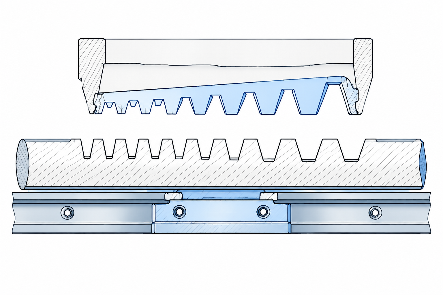
Geometrically, a rack is the generating rack of its mating gear made real. A straight-flanked tooth profile at the pressure angle — 20 degrees in the dominant metric system, with other angles in specific legacy or compact designs — is conjugate to the involute gear: as the pinion rolls along the rack, the planar flanks mesh exactly, which is why the rack tooth can be a flat surface at all. Module, pressure angle and addendum must match the mating pinion, and the functional requirements follow: profile accuracy for smooth engagement, pitch accuracy for uniform transmission, and tooth alignment to the mounting datum so the mesh does not tighten and loosen along the travel.
The family is broader than the straight bar. Sector gears — a gear cut through only an arc of its circumference — share the same tooth forms and serve limited-rotation drives, and rack segments, the short lengths of toothed bar joined end to end into a long guide way, are the form most linear-drive customers actually buy. Steering racks, hoist racks, machine-tool feeds and gate operators all pose the same manufacturing question: a repeating straight tooth form, a long workpiece, and a pitch that must accumulate gently over the full length.
Blank condition decides much of the process plan before any cutter touches steel. Racks are produced both from cold-drawn bar and flat stock — the economical blank for general linear-drive racks, whose consistent section means uniform chip load per tooth — and from forgings, which dominate steering and other high-load applications in medium-carbon alloy steel but arrive with scale, decarburized skin and stock variation. And in either form, the rack is a slender workpiece — a length-to-section ratio that makes support, not cutting force, the first engineering problem.
Broaching, Milling or Grinding: the Rack Cutting Routes
Three processes realistically cut rack teeth, and they divide the work along three axes: how the teeth are generated, what volume justifies the tooling, and where the part sits in the heat-treatment sequence. Broaching generates every tooth in one stroke from a form tool — the tooth profile and pitch live in the broach, ground and inspected once, then copied onto each part. Milling generates teeth discretely, one tooth or one gang of cutters at a time, indexed by the machine. Form grinding finishes hardened teeth with a dressed abrasive profile — the precision end of the chain, and the only route that corrects geometry after hardening.
| Route | How teeth form | Best suited to | Boundary |
|---|---|---|---|
| Broaching | All teeth cut in one stroke by a form broach | Constant tooth form, higher volumes, slender bars well supported | One broach cuts one constant profile; dedicated tooling per rack design |
| Milling | Indexed per tooth or by gang cutters | Low and medium volumes, changing designs, large racks beyond stroke length | Cycle time scales with tooth count; profile consistency is machine-dependent |
| Form grinding | Abrasive profile finishes the flank | Hardened teeth, tight accuracy, variable-ratio forms | Finishing process, not bulk stock removal; costliest per unit of material moved |
It helps to see the rack as the special member of the gear family. For round gears, hobbing is the volume process, and the comparison our broaching vs hobbing article draws for cylindrical parts — continuous generation versus form copying — does not even reach the rack, because a hob needs a rotating blank. On a rack the choice collapses to broaching, milling or grinding, and the same logic we apply to broaching vs milling for keyways and profiles governs: the broach wins when volume amortizes form tooling and the geometry is fixed; the mill wins when flexibility or part length dominates.
The Steering Rack Question: Constant Ratio vs Variable Ratio
No rack application is discussed more, or misunderstood more, than steering. The steering rack of a rack-and-pinion steering system is the classic automotive broaching workpiece — and the reason is geometric. A constant-ratio steering rack carries the same tooth form from one end of its travel to the other: the profile the pinion meshes with at center is the profile it meshes with at full lock. That is exactly what a form broach produces. Every finishing tooth on the broach carries the identical profile, so one stroke cuts every tooth of the rack to the same inspected form, and piece ten thousand meshes like piece one.
The honest boundary arrives with variable ratio. Modern steering tuning often asks for a ratio that changes along the travel — quicker on center, slower toward the ends, or the reverse — which means the tooth form itself varies from tooth to tooth along the rack. A broach cannot do this: its cutting teeth are fixed in sequence on a steel blade, and the profile they cut at the start of the stroke is the profile they cut at the end. Variable-ratio racks are therefore a grinding application: CNC rack grinders dress a wheel form that can change along the stroke, and that is where high-precision variable-ratio production lives.
Where broaching genuinely sits in steering supply chains is threefold: constant-ratio racks, where the economics of one-stroke tooth generation apply at full force; pre-forming and roughing of variable-ratio racks, where a broach removes the bulk stock to a uniform constant form and the grinder moves only the finishing allowance; and the non-steering rack family at large — linear actuators, hoists, gates, machine feeds — where constant form along the length is the norm rather than the exception. Suppliers who quote “steering rack broaching” without drawing this line are quoting a boundary they have not examined.
Tooling the Cut: Long-Part Support, Nesting and Indexing
A rack is broached as surface work: the part is clamped stationary on a long bed and the broach passes along the tooth line, or the part rides a continuous chain past stationary broaches at the highest volumes. Because the workpiece is slender, fixturing carries the operation. The bar must be supported along its full length — a bearing-length nest or way-mounted support that backs the stock under every cutting tooth — with hold-downs spaced so the horizontal cutting force cannot lift or bow the bar between supports. The slender-workpiece discipline is the same one our barrel broaching article develops for long shafts: support close to the cut, control the deflection, and treat the fixture as the machine’s extension. A bar that springs during the stroke hands the finishing teeth a varying depth of cut, and pitch and profile errors follow that no tool accuracy will remove.
Volume economics on a rack line come from cutting more than one part per stroke, and there are two configurations. The first is nesting: multiple bars clamped side by side in the fixture, cut simultaneously by a wide broach body carrying a row of identical tooth forms — one stroke, several finished racks. The second is string broaching along the stroke direction, where shorter parts are queued in series on a long bed so loading, cutting and unloading overlap. Which one fits depends on part length versus stroke length, but both exploit the same property: once the broach section is engaged, additional parts at the same station cost cycle time only marginally.
Indexing enters when the rack carries teeth on more than one face. A double-face rack is broached on its first tooth line, then the fixture indexes the part — typically 180 degrees about the bar axis — against a positive location, and the second pass cuts the opposing teeth. The index datum, not the operator’s eye, sets the relationship between the two tooth lines: phase, parallelism and distance across the bar all trace to the indexing fixture, and it must be re-verified after every conversion, because a mis-phased double rack fails only at assembly on the customer’s floor.
Pitch Accumulation and Tooth Profile: the Accuracy Problem
Rack accuracy has two distinct components, and they fail differently. Tooth profile accuracy — the shape of each flank — is copied from the broach’s finishing teeth, so it is fixed by tool manufacture and inspection and repeated identically on every part until the tool wears or is reground. Pitch accuracy divides further: single-pitch error, tooth to tooth, again largely a property of the broach, and pitch accumulation over the rack’s full length, which is the genuine difficulty on a long rack and the one broaching does not solve by itself.
Accumulated pitch over a long rack traces to three sources: the cumulative pitch accuracy of the broach itself, measured once on the tool; the straightness of the datum the part is clamped against — the mounting face or guide surface machined before the tooth cut, because a bar clamped on a bowed datum delivers bowed teeth; and the parallelism between that datum and the machine’s stroke direction. Two of the three live upstream of the broach or in the setup, which is the honest answer to engineers who ask what pitch accumulation a broaching machine “holds”: the machine contributes its stroke-to-datum parallelism, and the rest is tool and fixture quality. All three are inspectable, and a rack process plan should name the owner of each.
Very long travel drives manage accumulation by segmentation rather than by heroic single-piece tolerance. Rack segments are produced, measured, and matched so that the pitch error at the end of one segment meets the beginning of the next; mating ends are finish-matched, marked for orientation and direction, and installed in the matched order. Inspection is linear — a pitch-measuring instrument traverses the tooth line tooth by tooth, profiles compare against the master form, and the joints get a system-level check once segments are assembled. The broach’s contribution — identical teeth from a single inspected form — is what makes this matching manageable, because segment-to-segment variation starts from a common tool.
Cycle Time and the Economics of One Stroke
The economic case for rack broaching is the same arithmetic that governs every form-tooling decision, sharpened by tooth count. A milled rack pays an index-and-cut cycle for every tooth or gang of teeth: cycle time grows with tooth count, and profile consistency becomes a running function of machine condition and setup discipline. A broached rack pays one stroke. The teeth, however many the drawing calls for, finish in a single pass at a cycle time set by stroke length and cutting speed — which is why long, densely toothed racks are where broaching’s per-part advantage is widest.
Against that stands the front-loaded cost: a broach is a dedicated, part-specific tool, ground to the customer’s module, pressure angle and tooth form, plus a fixture engineered to the blank. The break-even is volume-driven, and the correct comparison is annual demand against the total cost of the milling route — machine hours, tooling and the inspection labor that chasing profile consistency on an indexed process consumes. Where designs change frequently or volumes are modest, milling remains the sensible route and nothing on this site argues otherwise; where a rack design is stable and the volumes run, the one-stroke process amortizes its tooling and compounds its advantage every stroke thereafter. Regrinding extends the arithmetic: each sharpening restores the cutting edges at the cost of a small length reduction, so tool life is planned in regrinds and per-part tooling cost is quoted over that full life.
Where Broaching Sits in the Heat-Treatment Sequence
High-load racks — steering racks above all — are hardened on the tooth flanks, usually by induction hardening, and the sequence question that governs every hardened workpiece governs the rack: cut soft, cut hard, or split. The standard high-volume answer is a three-stage chain: broach the tooth form in the soft condition, where the steel cuts freely and the tooling economics work; induction harden the tooth zone; then finish by form grinding, which corrects the distortion hardening introduced and brings the flanks to final accuracy. This broach-harden-grind chain is the honest default, and it places broaching as the tooth-generating step, not the final-accuracy step, in hardened-rack production.
Hardened flanks are, with a controlled exception, grinding’s territory. Carbide-toothed hard broaching exists as a corrective operation — a small, closely defined allowance taken after hardening to pull a distorted tooth zone back toward the broach’s ground form — but it is a finishing recalibration validated against the actual hardness distribution, never bulk stock removal, and never a substitute for the grind on precision racks. Where the application’s accuracy class allows finishing in the soft state, the chain shortens to broach-and-harden; where the drawing demands hardened precision, the rack leaves the broaching machine as an accurate pre-form and the grinder owns the last word. The material state at the cut, verified, decides the process — not the label on the route sheet.
The Machine: Why Racks Belong on a Horizontal Bed
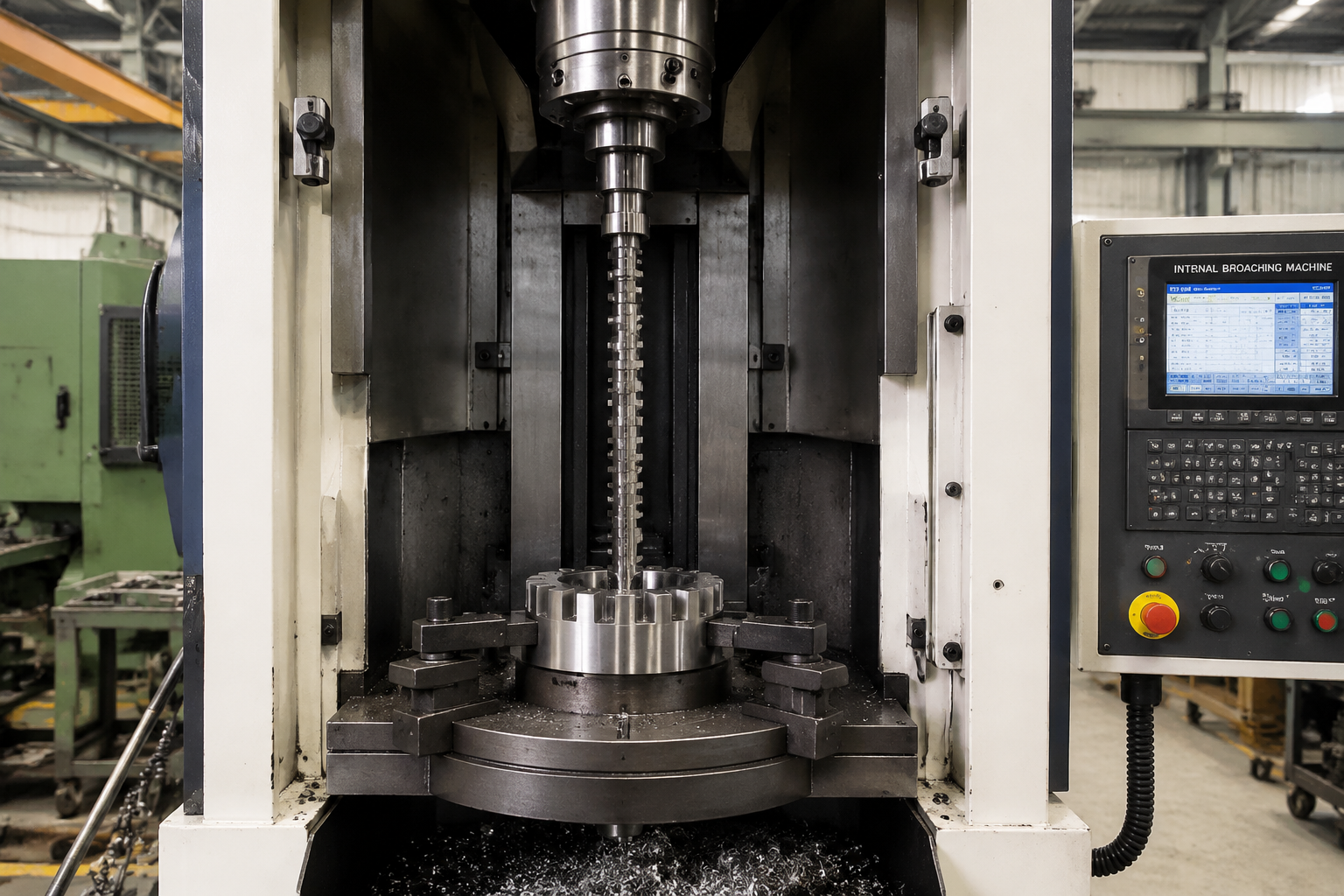
Part length dictates machine architecture. A rack is the longest workpiece most transmission shops cut teeth in, and the layout that takes it naturally is the horizontal broaching machine — long bed, workpiece supported along its full length at working height, broach passing along the tooth line, loading and unloading without lifting a heavy bar into a vertical envelope. Our horizontal broaching machine guide covers the architecture in detail, including the surface and continuous configurations that long constant-section forms like racks call for. The properties that matter for rack work specifically are usable stroke length against the tooth line, fixture-mounting way surface adequate to full-length support, and enough ram power to push the forming section through the blank’s worst-case stock — all quoted against the actual drawing, not a catalog class.
At the throughput extreme, continuous broaching carries the same logic to line scale: racks or rack segments riding a chain track past stationary broach sections, with loading overlapping cutting so the station never idles. The machine family overview on our broaching machines page maps the horizontal, vertical and continuous layouts against workpiece families, and the rack sits squarely in the long-part corner of that map.
Frequently Asked Questions
Can a variable-ratio steering rack be broached?
Not to final form. Variable ratio means the tooth profile changes from tooth to tooth along the travel, and a broach cuts one constant form along its whole stroke. Variable-ratio racks are ground on CNC rack grinders, whose dressed profiles can vary along the stroke. Broaching still contributes on these parts — as high-productivity roughing and pre-forming to a constant form — but the finishing operation belongs to grinding, and any process plan should say so plainly.
Can rack teeth be broached after hardening?
Only as a controlled exception. The standard chain for hardened racks is broach in the soft state, induction harden the tooth zone, and finish by form grinding. Carbide hard broaching can take a small corrective allowance on hardened teeth, but it is a recalibration step validated against the real hardness distribution — never the bulk cutting operation, and never the final word on a precision flank.
What controls accumulated pitch error over a long rack?
Three things, with distinct owners: the cumulative pitch accuracy of the broach, fixed at tool manufacture and verified on the tool; the straightness of the datum face the rack is clamped against, machined upstream; and the parallelism between that datum and the machine’s stroke direction, which is the machine’s contribution. Very long drives are managed at assembly, as matched segments, rather than fought on a single bar.
When does milling a rack make more sense than broaching it?
At low volumes, while the design is still changing, or when the rack is longer than any practical single stroke and the accuracy class allows a joined solution. Milling needs no dedicated form tool and absorbs design revisions cheaply; its costs appear per part — cycle time that grows with tooth count, and profile consistency that depends on machine condition and setup discipline. Once a rack design is stable and volumes are sustained, one broach stroke reverses that arithmetic.
Plan Your Rack Production
The rack shares its workpiece logic with the rest of our broaching case library: the long-part support discipline of barrel broaching, the tooth-form copying economics of special shaft tooth broaching, and the form-versus-generation routing questions our gear-family comparisons cover. The pattern is constant: identify what repeats along the part, cut it with one inspected form, and hand the hardened finishing to the process that owns it.
If you produce racks — steering racks, linear-drive racks, rack segments or sector work — send us the drawings with material specification, hardness at the proposed cutting stage, tooth data and annual volumes. Our engineers will review whether your tooth form is broachable or belongs to the grinder, recommend the broach-harden-grind sequence or its shorter variants, and work out nesting, support and cycle time against your demand. Start with the horizontal broaching machine guide, or contact our engineering team directly with your workpiece details.