

Engineering concept illustration of two process routes. It is not a dimensional process drawing, a customer part or a photograph of a BroachingMach product.
Broaching vs milling is not a contest between a “fast” process and a “flexible” process. For an internal keyway or repeated profile, the useful decision starts with the drawing: can the tool enter and leave the feature, is the profile stable across the part family, what datum controls its position, and how will the feature be inspected?
A progressive-broaching candidate and a milling candidate commit the review to different tool, machine, fixture and validation questions. The responsible providers must define those route requirements from the released drawing. Neither process is automatically the lower-cost or higher-accuracy choice on every part.
This guide focuses on controlled internal keyways and repeated internal profiles. For keyway-broaching fundamentals, start with Keyway Broaching: The Complete Guide. For a closed-end keyway, use the dedicated Blind Keyway Broaching guide; its relief and retraction decisions are not interchangeable with a through-broach route.
The Short Answer
For a through feature, a progressive-broaching candidate and a milling candidate can both enter a route review when the released drawing, part family, fixture and inspection requirements are available. A blind end, restricted exit or changing feature does not select a method by itself; it creates additional questions for the responsible provider.
Those are starting hypotheses. Before selecting either route, confirm the exact profile, material condition, pre-machined opening, through/blind status, protected surfaces, annual mix, fixture datum and inspection method.
Broaching and Milling Commit the Process in Different Ways
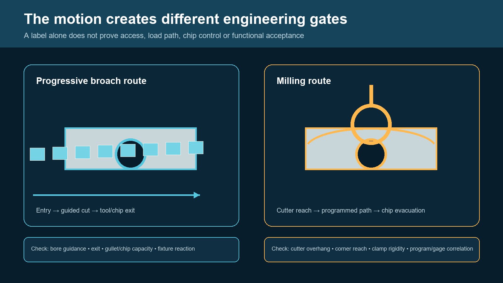
A progressive broach distributes stock removal across successive teeth. Milling uses a rotating cutter and a programmed path. The concept does not imply a universal feed, force, depth or tool size.
Progressive broaching
For a conventional progressive-broaching candidate, ask the responsible provider to review the tool, prepared opening, guidance, machine stroke, fixture support, chip handling and exit/handling path as one system. The article does not prescribe a tooth sequence or process setting.
This makes broaching powerful for a released, repeatable feature. It also means that a nominally similar revision—such as a changed width, depth, corner condition, material state or datum—can require a new tooling and validation decision. A catalog label does not prove that a particular keyway broach fits the bore guidance, length, material and machine interface of the part.
Milling
For a milling candidate, ask the responsible provider to review the cutter, programmed path, machine, fixture and datum scheme against the required feature and its variants. This page does not infer flexibility or a replacement for dedicated tooling from the existence of a program or cutter change.
The review should ask whether the cutter can reach the feature, whether the machine and fixture can support the route, how chips are handled, and how the programmed path preserves the functional datum. These are provider- and drawing-specific questions, not universal milling outcomes.
Gate 1: Can the Feature Support a Progressive Tool Path?
The first selection gate is physical access, not production quantity.
Through features
A prepared through bore may offer an entry and far-face exit for review of a conventional progressive-broaching route. The complete system still needs a provider review of the tool connection, handling, part support and chip path; through access alone does not approve a route.
Milling can also make a through internal keyway or form. Its advantage may be that the part already resides on a machining center or that a family of variants makes dedicated broaching tooling premature. Compare the entire route—not merely the cutting stroke.
Blind or restricted-end features
A conventional progressive broach cannot simply stop inside a blind keyway and reverse. The cutting edge and chips need a controlled clearance path. Depending on the feature, a keyseater, slotter, CNC single-point method, EDM or an application-specific controlled-stroke approach may be the safer candidate. See the blind-keyway guide for the relief, ramp-out and chip-management questions.
For a restricted-end layout, milling is a candidate only if the cutter can reach the depth while the actual fixture, cutter stiffness, corner geometry, chip path and return path can be validated. Do not select a route just because the feature is called “blind.”
Profile access is more than through or blind
Review these drawing questions before estimating cost or capacity:
- Does the pre-machined opening provide enough guide and entry space?
- Can a progressive tool clear the far face without striking a shoulder, fixture or adjacent feature?
- If milling, can the cutter reach the bottom and sidewalls without unsupported length dominating the cut?
- Is there a real chip and coolant exit path throughout the operation?
- Can the finished feature be measured relative to the actual functional bore, face or angular datum?
Gate 2: Is the Part Family Stable Enough for Dedicated Tooling?

Use the controlled part family and process constraints to select a candidate route. The matrix is not a tolerance, throughput or cost guarantee.
For a dedicated broaching candidate, record the profile, material condition, part-family variants, bushing/fixture assumptions and maintenance/change-control requirements. This article does not claim that dedicated tooling reduces setup decisions or guarantees a production result.
For some part families, different widths, depths, angular positions or related milled features can be screened through a cutter, program and fixture change rather than a new progressive tooth sequence. That is not an outcome promise: it may also require setup, program verification, cutter-condition and inspection review. The route decision comes from the controlled part family, not a generic “low-volume versus high-volume” slogan.
Review:
- annual demand, batch size and demand volatility;
- number of actual profile and bore variants;
- likelihood of drawing revisions or new material conditions;
- available machine hours and whether another operation becomes the bottleneck;
- spare-tool, regrinding and change-control requirements;
- time spent loading, cleaning, deburring and inspecting outside the cut.
For a custom progressive route, the controlled drawing, blank condition and machine interface belong in a broach-tooling design review. A machine nameplate or a broad process description cannot replace a tool-and-part validation.
Gate 3: Which Datum, Fixture and Feature Relationship Matter?
An internal keyway can be dimensioned from a bore, a face, a tooth pattern, another slot or an external feature. The process must preserve that relationship from location through inspection.
The inspection examples in this article are screening categories only. The drawing owner and qualified inspection function must define the accepted characteristics and correlation method for the actual part; this article does not prescribe a gage, CMM method or acceptance result.
For either candidate, ask the responsible provider to show how guidance or workholding, support, tool axis and the programmed path will preserve the drawing datum. The actual fixture and inspection strategy must be agreed for the part; this article does not infer a result from a process label.
Do not infer inspection quality from a tool description. First-off inspection should check the specified width, depth, angular relationship, form and surface condition against the controlled datum. Where a functional gage, pins/span, CMM or another method is required, correlate the production method with the customer’s acceptance approach before releasing the route.
Compare the Whole Tool–Machine–Fixture System
| Decision area | Progressive broaching candidate | Milling candidate | Validation question |
|---|---|---|---|
| Tool motion | Multi-tooth linear traversal through a guided feature | Rotating cutter follows a programmed path | Can the actual tool clear entry, walls, bottom and exit? |
| Workpiece presentation | Bore/fixture guides tool and resists the load path | Fixture maintains datum while cutter reaches the feature | Which surfaces locate, support and resist rotation? |
| Chip route | Gullet capacity and full traversal must clear chips | Cutter engagement and coolant must evacuate chips | Where do chips go at the deepest point? |
| Change control | Profile changes can require a new tool/qualification | Program, cutter and setup changes still require validation | Which drawing variations are approved in the part family? |
| Inspection | Verify feature against the released tool/fixture datum | Verify feature against programmed and fixture datum | Does the gage reproduce the functional requirement? |
The force/stroke review should use the actual material, engagement, feature length, tool condition and fixture path. The broaching-machine tonnage guide explains why a rated machine capacity is only one input—not proof that a particular tool and part are suitable.
Cost and Timing: Build a Route Model, Not a Universal Break-Even
Broaching can concentrate engineering and tooling commitment up front. Milling can distribute more of the route into programming, cutter selection, setup and repeat verification. Both also carry costs beyond cutting: incoming blank control, fixture design, handling, coolant/filtration, tool maintenance, deburring, gaging, rework risk and documentation.
Use a route model that tracks what is actually different for the part family:
- freeze the controlled drawing and variant list;
- define the pre-machined opening, material and heat-treatment stage;
- identify all tool, holder, bushing and fixture interfaces;
- model loading, cutting, cleaning, deburring and inspection as separate events;
- run representative normal and worst-case samples;
- compare the accepted process, not an unloaded machine-cycle estimate.
This method avoids turning a generic internet break-even number into a procurement decision.
A Practical Selection Workflow

The checklist identifies information needed to evaluate a route. Final tooling, machine, fixture, inspection and production commitments require drawing review and representative-part validation.
- Define the exact internal keyway or profile and identify what is out of scope.
- Mark the controlling bore, face, angle and protected surfaces on the drawing.
- Confirm through/blind access, tool exit, bottom condition and chip route.
- Separate stable released variants from future or uncertain design changes.
- Evaluate progressive broaching, milling and any restricted-access alternative against the same fixture and inspection requirements.
- Review material condition, blank variation and heat-treatment stage before specifying a tool route.
- Test representative parts and compare results after full release from the fixture.
- Document the accepted tool, program, fixture, gage and reaction plan for future changes.
Information Needed for an Engineering Review
Send the controlled part drawing and CAD model, the profile/bore dimensions, through or blind condition, material and heat-treatment state, pre-machined opening and stock condition, functional datums, protected surfaces, required inspection method, annual volume and variant mix, available machine interfaces, current tooling/fixture details and representative normal/worst-case parts.
These inputs allow the tooling, machine, fixture, chip path and inspection plan to be reviewed as one system. They do not guarantee a tooling solution or a production result before a sample and validation plan are agreed.
Frequently Asked Questions
Is broaching always better than milling for an internal keyway?
No. A through feature with a stable part family may suit a progressive broach, while design variation, existing machining setup or restricted access can support a milling route. Validate the actual drawing, part mix, fixture and inspection method.
Can milling replace a progressive broach on a blind keyway?
It can be a candidate, but the cutter must reach the blind end with adequate stiffness and a workable chip path. Milling, keyseating, CNC single-point broaching and EDM should be compared against the specific end condition. The blind-keyway guide covers the access questions in more detail.
Does a dedicated broach remove the need for inspection?
No. Tool geometry is only one contributor. Blank condition, guidance, fixture location, tool condition, chip control and measurement datum all affect the released feature.
Should tooling be selected from a nominal keyway size alone?
No. The bore, usable length, keyway geometry, material condition, access, machine interface, part support and inspection requirement are also needed.
Request a Broaching or Milling Route Review
If you are evaluating a repeatable internal keyway or profile, send the drawing and representative-part information. For a potential BroachingMach broaching route, provide the controlled drawing and application inputs so the tool, machine, fixture, chip-path and inspection questions can be reviewed before a route is proposed. Review any milling route with the provider responsible for that process.
Editorial Scope Note
Current search results and public competitor pages establish that engineers compare these method families. They do not establish BroachingMach machine, tooling, milling-service, cost, accuracy or production-result capability. This page is therefore a drawing-led screening guide, not a specification or performance comparison.


