

Conceptual illustration of a single-point tool cutting a blind internal keyway in a CNC setup. It is illustrative, not a dimensional process drawing or a photograph of a BroachingMach product.
Blind keyway broaching creates an internal keyway that stops before the far end of a bore. Because the tool cannot pass completely through the workpiece, the process must control the stopping position, provide somewhere for chips to go and retract without driving the cutting edge into packed chips.
The most robust design normally includes a relief groove, cross-hole or open space beyond the end of the keyway. When the part cannot include relief, a specialized single-point tool and validated CNC path may be able to cut and retract safely, but it should not be treated as a universal solution.
This guide compares blind and through keyways, CNC lathe and mill setups, relief strategies, tooling, inspection and the alternatives to consider before committing to the process.
Blind vs Through Keyway Broaching

A through keyway gives the broach and chips an exit path. A blind keyway stops inside the bore and needs controlled end geometry and chip clearance.
| Factor | Through keyway | Blind keyway |
|---|---|---|
| Feature end | Opens through the opposite face | Stops before an internal shoulder or closed end |
| Tool exit | Tool can pass through the workpiece | Tool must stop and retract |
| Chip path | Chips can leave with the tool | Chips can collect at the keyway end |
| Typical tooling | Progressive push/pull keyway broach, CNC single-point tool or keyseater | CNC single-point/indexable tool, slotter/keyseater or specialized controlled-stroke system |
| End geometry | Determined mainly by part length and tool travel | Relief groove, cross-hole, ramp-out or a validated no-relief strategy |
| Process risk | Alignment, force and finish | All through-keyway risks plus bottoming, chip packing and retraction damage |
A standard progressive keyway broach removes the profile as successive teeth pass through the bore. It is naturally suited to an open, through feature. Blind work usually changes the cutting action: one cutting edge makes repeated controlled strokes, removing a small amount on each pass until the programmed depth is reached.
For the general keyway process, see Keyway Broaching: The Complete Guide. The rest of this article focuses only on closed-end features.
Why Blind Keyways Are More Difficult
The Tool Cannot Clear the Part
At the end of a through cut, the broach and its chips leave the workpiece. In a blind bore, the cutting edge approaches an internal shoulder or the programmed bottom of the keyway. The machine must decelerate and stop before contact, then move the edge away from the newly cut surface before retracting.
Chips Accumulate at the Closed End
Every stroke forms another chip. If the end space is too small, chips compact into a hard mass. The next stroke can drive the insert into that mass, raising load, lifting the insert in its pocket, chipping the edge or causing a machine alarm.
Coolant alone does not guarantee evacuation. A jet can move chips deeper into an undersized pocket. Relief shape, gravity, nozzle direction, chip size and the retraction path must work together.
Tool Overhang Affects Alignment
A tool reaching deep into a bore behaves like a cantilever. Holder clearance, tool length and cutting force can create deflection at the edge. A small angular error at the holder becomes a larger position error at the cutting point.
The Keyway Bottom Is a Functional Feature
The drawing must define where the usable keyway ends, what radius or runout is acceptable and whether a relief groove can interrupt the bore. “Blind keyway depth” is incomplete unless the datum, bottom shape and inspection method are also specified.
Process Options for a Blind Keyway
CNC Single-Point or Indexable Broaching
A rigid holder carries one cutting edge into the bore. With the spindle oriented and normally stopped, the machine's linear axis moves the tool through a cutting stroke. The tool then moves clear of the cut, retracts and advances for the next pass.
This method can keep the part in the CNC lathe or machining center used for earlier operations, protecting datum relationships and reducing a secondary setup. It is particularly useful for prototypes, families of keyway sizes and volumes that do not justify a dedicated progressive broach.
The tradeoff is cycle time and process sensitivity. Many strokes are required, and tool alignment, machine-axis motion, holder rigidity and chip control directly affect the result.
Keyseating or Slotting
A keyseater or slotter uses a controlled reciprocating tool to generate the slot progressively. The method can be well suited to blind internal keyways because stroke length and end position are directly controlled.
It may provide better access or chip handling than adapting an unsuitable machine, but it adds another setup unless integrated into the production route. Evaluate workholding, datum transfer, stroke capacity and inspection rather than comparing machine names alone.
Dedicated Controlled-Stroke Broaching System
Special CNC keyway or groove machines can combine rigid guidance, programmed stroke and purpose-built fixtures. This may be the stronger production solution when the part family, annual volume and quality requirement justify dedicated equipment.
Machine capability must be confirmed from the real part and tool. A product name containing “keyway,” “groove” or “CNC” does not prove that it can stop, clear chips and retract safely in every blind geometry.
EDM or Another Alternative
Wire or sinker EDM, shaping, slotting, milling with suitable access or a design change to a through keyway may be lower risk when:
- The material is hardened or difficult to cut.
- No chip-relief volume is available.
- The bore is too small for a rigid holder.
- The keyway is unusually deep relative to tool section.
- Bottom geometry is more important than cycle time.
- Production volume cannot justify dedicated tooling.
Relief and Chip-Control Designs
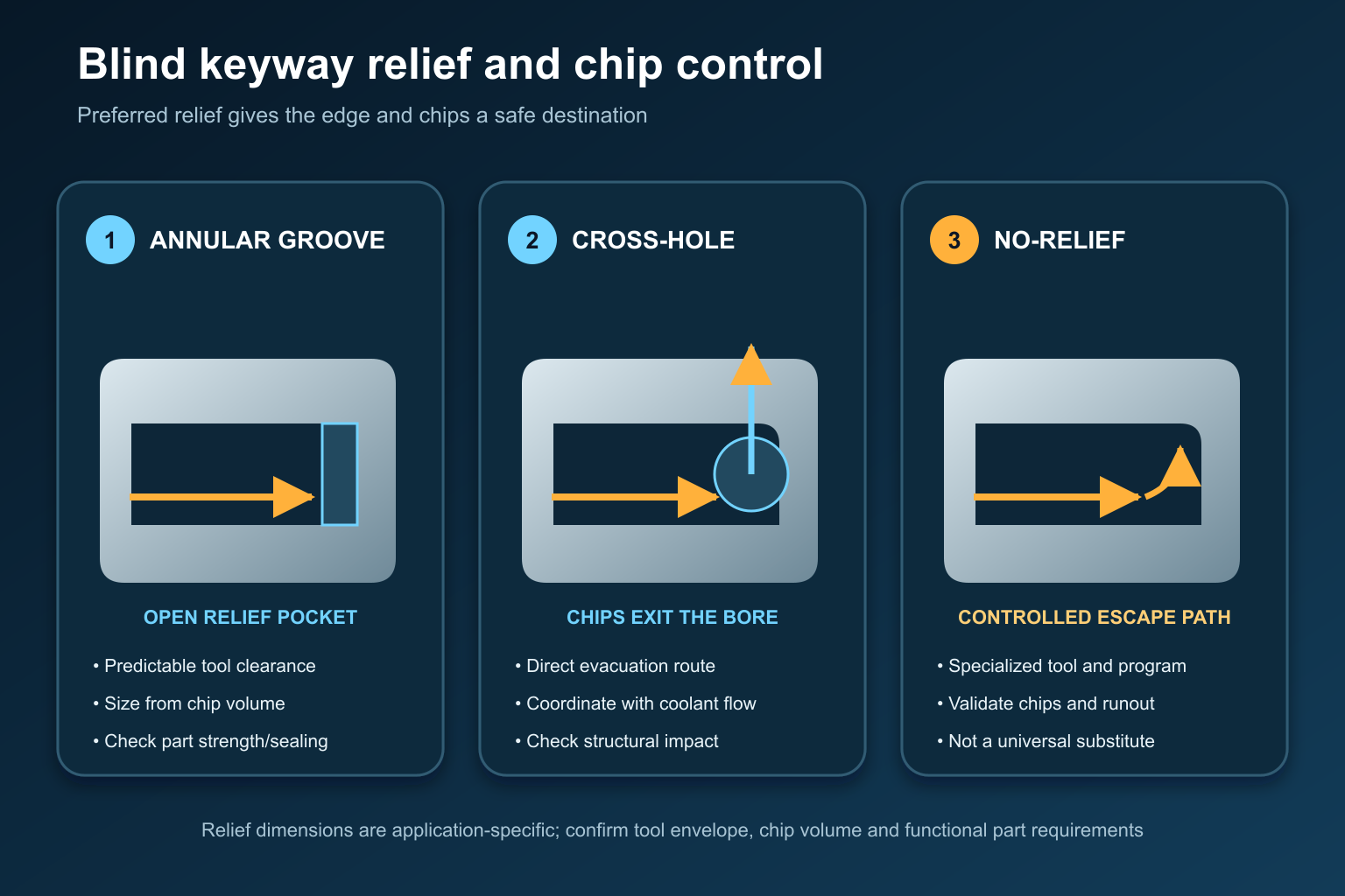
An annular groove or cross-hole gives chips a defined destination. A no-relief method needs specialized tooling and a validated toolpath that moves the cutting edge away before retraction.
Annular Relief Groove
An internal groove beyond the functional keyway end gives the cutting edge and chips an open pocket. It is usually the most predictable arrangement when the part can tolerate the groove.
The groove must be sized from the tool envelope, chip volume, programmed stop variation and part strength. Supplier examples can be useful starting references, but their dimensions are not universal design rules.
Cross-Hole or Window
A cross-hole can let chips and coolant pass out of the bore instead of accumulating at the bottom. Its position must align with the cutting path without weakening a critical section or violating sealing requirements.
Programmed Ramp-Out
Some single-point systems move the tool away from the keyway as it approaches the end of the stroke, creating clearance before retraction. This can reduce edge rubbing and help move the chip, but it changes the keyway runout geometry.
No-Relief Cutting
Specialized tools and programs may cut a blind keyway without a separate groove or cross-hole. This is an application-specific capability. It requires controlled chip formation, a safe escape path for the edge, repeatable axis motion and proven clearance at the bottom. Do not remove relief from the part merely because one supplier demonstrates a no-relief example.
CNC Lathe vs CNC Mill
CNC Lathe
A lathe can hold the bore axis horizontally, allowing gravity to help chips fall away from the keyway end. The spindle must be oriented and held at the required angular position. The toolholder, boring-bar sleeve or turret station must keep the insert square to the bore.
The part can often be turned, bored and broached in one clamping. This is valuable when keyway position must relate closely to a machined diameter or face.
Vertical Machining Center
On a vertical mill, a vertical blind bore can collect chips in the relief area. Coolant may circulate them without removing them. A sufficiently open cross-hole, evacuation cycle or different part orientation may be necessary.
The mill still offers flexible fixturing and axis control, particularly when the keyway must align with other milled features. The decision should be based on chip direction, tool overhang, holder access and datum control—not on machine availability alone.
Horizontal Machining Center
A horizontal spindle can combine the flexible programming of a machining center with more favorable chip fall. It may be a better orientation for deep blind features, provided the holder, axis force and stroke remain suitable.
Setup Workflow
- Define the bore, keyway width, radial depth, usable length, bottom/runout geometry and angular datum.
- Decide whether the drawing can include an annular groove, cross-hole or other relief.
- Select the process from material condition, feature access, volume and required cycle time.
- Confirm that the machine axis can deliver the required stroke and cutting force without relying on spindle rotation.
- Minimize tool overhang while preserving bore and shoulder clearance.
- Indicate the cutting edge in both planes and verify spindle orientation or fixture angle.
- Program cutting, clearance, retraction and chip-evacuation movements as separate events.
- Start with conservative stock per stroke and validate force, chip form and finish on representative parts.
- Inspect the first-off part for width, depth, angular position, straightness and end geometry.
- Establish force/tool-wear limits and a chip-cleaning response before production.
For a purpose-designed tool, send the finished part and machine interface to the broach tooling design team. Standard keyway broaches should not be assumed suitable for a closed-end feature without an application review.
Tool, Holder and Machine Considerations
Cutting Edge and Holder
The tool must resist deflection while fitting through the bore. Edge geometry, substrate and coating depend on the workpiece material, hardness, stock per stroke and coolant strategy. An indexable insert can simplify edge replacement, while a solid tool may provide a different stiffness or size range.
Keep the holder connection clean and repeatable. Tightening a sleeve or set screw can tilt a long tool. Indicate at or near the cutting location rather than assuming that the holder body represents edge alignment.
Force and Motion
Do not size the process from a generic machine-tonnage label. Keyway width, stock per stroke, material, edge condition and engagement length affect load. The principles in our broaching-machine tonnage guide remain relevant even when the stock is removed over repeated strokes.
Coolant and Chips
The fluid must reach the cutting edge, lubricate the interface and carry chips toward a real exit. Review viscosity, lubricity, filtration and delivery using our broaching cutting-fluid guide.
If load rises, chips change shape or the insert begins to chip, stop and investigate. Continuing until failure can damage the holder, workpiece and machine. The checks in How to Avoid Broach Breakage provide a broader troubleshooting sequence.
Common Problems and Corrective Direction
| Symptom | Likely area to inspect | Corrective direction |
|---|---|---|
| Insert chips during retraction | Edge is not fully clear; packed chips; holder tilt | Separate clearance and retract moves; enlarge/clean relief; re-indicate tool |
| Load rises through the cycle | Chip accumulation; excessive stock per stroke; dull edge | Inspect relief and chip form; reduce load; service the edge |
| Keyway tapers or wanders | Tool deflection; excessive overhang; datum movement | Shorten/stiffen setup; improve holder and workholding |
| Scratches on return | Tool rubs the cut during retraction | Program positive clearance before the return motion |
| Damaged keyway bottom | Tool bottoms out; stop variation; insufficient relief | Review stroke limit, deceleration, relief and tool envelope |
| Width or angle varies | Insert seating, spindle orientation or fixture repeatability | Clean and inspect pocket; verify orientation and angular datum |
These symptoms are diagnostic starting points, not proof of one cause. Record cutting load, chip condition, tool position and inspection results before changing multiple variables at once.
Selecting the Right Method
Use a progressive through broach when the keyway can open through the part and volume supports dedicated tooling. Use CNC single-point broaching when the feature is blind, the machine can provide controlled linear motion and retaining the part in one setup adds value.
Choose a keyseater, slotter or dedicated keyway machine when stiffness, stroke control or production demand exceeds the practical capability of the available lathe or mill. Compare EDM or a design change when access, material hardness or bottom geometry makes chip-forming methods unstable.
BroachingMach offers keyway broaching machine categories and application-specific machine/tooling review. The correct platform depends on the drawing rather than the label “blind broaching.”

BroachingMach CNC high-precision inner-groove horizontal broaching machine shown as a related controlled-stroke platform. This image does not establish suitability for every blind-keyway geometry; the part, tool, chip path and stroke must be reviewed.
Information Required for an Engineering Review
Provide:
- Finished part drawing and 3D model if available.
- Bore diameter, keyway width, radial depth and usable length.
- Blind-end geometry, relief groove or cross-hole details.
- Material, hardness and heat-treatment condition.
- Required tolerance, surface finish and angular relationship.
- Annual volume, batch size and target cycle time.
- Available machine, axis orientation, stroke and holder interface.
- Current tool, insert and program information.
- Coolant, filtration and chip-control arrangement.
- First-off or failed-part measurements and photographs.
This information allows the feature, tool, holder, fixture, machine motion and inspection plan to be reviewed as one process.
Frequently Asked Questions
Can you broach a keyway in a blind hole?
Yes. Common methods include CNC single-point/indexable broaching, keyseating, slotting and specialized controlled-stroke machines. The design must provide a safe stopping, chip-control and retraction strategy.
Does a blind keyway always need a relief groove?
No, but relief is normally the more robust design. No-relief cutting requires specialized tooling and a validated toolpath; it should not be assumed possible for every material, depth or machine.
Can a standard keyway broach cut a blind keyway?
A conventional progressive push or pull broach is naturally suited to a through feature because the tool must pass through the workpiece. Blind work normally requires a different cutting method or specially engineered clearance.
Is a CNC lathe or mill better?
A horizontal lathe often helps chips fall away and can preserve turning datums in one setup. A mill may offer more flexible orientation and feature alignment. Choose from chip direction, holder stiffness, axis capability and datum requirements.
Can a hardened part be blind broached?
Some hardened-material applications are feasible, but hardness, stock, tool system, rigidity and expected life must be validated. EDM or another finishing process may be lower risk for very hard material or restricted relief.
What should be inspected first?
Inspect keyway width, radial depth, straightness, angular position, surface condition and the end/runout geometry. Confirm that the inspection datum matches the functional drawing datum.
Final Recommendation
Treat a blind keyway as a different process problem from a through keyway. Start with the end geometry and chip path, then choose the tool and machine. When the part allows it, design a relief that gives both the cutting edge and chips somewhere safe to go.
Send your drawing and production requirements for a review of the feature, tool, machine motion, relief and inspection method.


