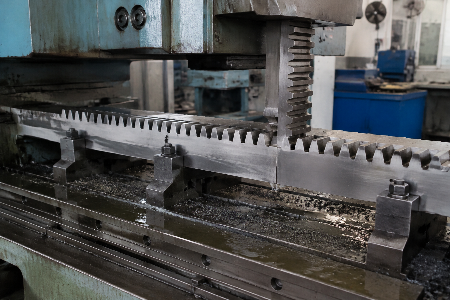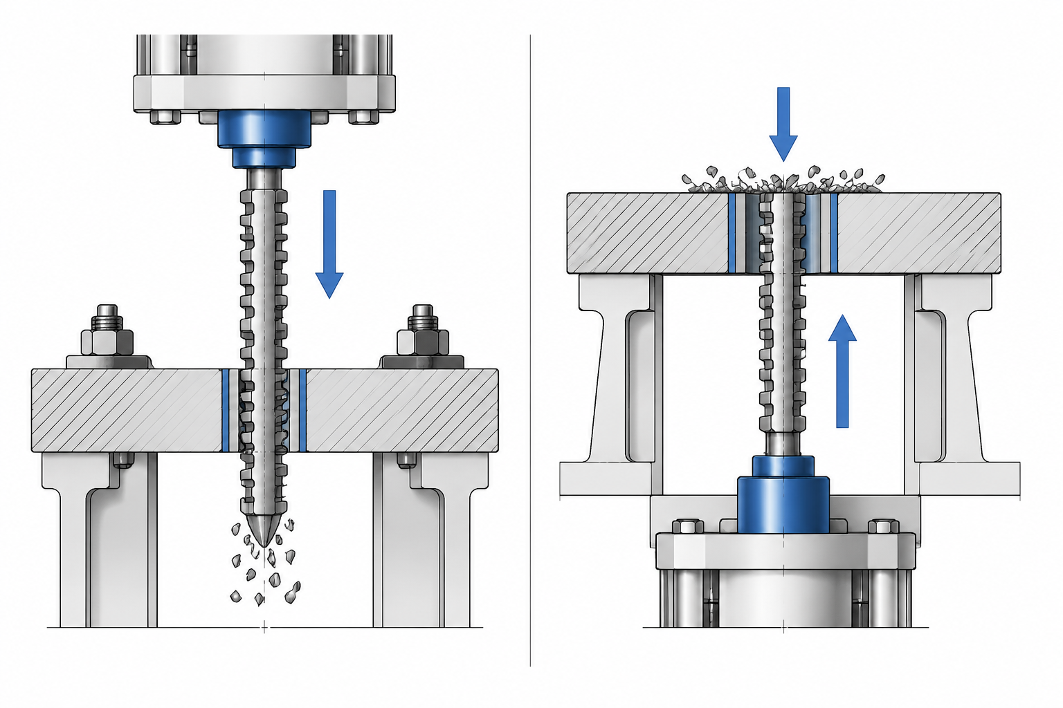
Inside every vertical internal broaching machine, the same event takes place: a multi-tooth broach is drawn through a pre-machined hole, each tooth lifting its share of the material until the finished keyway, spline or profile emerges in one pass. What separates one machine from the next is not the cut — it is the direction. A pull-down machine draws the broach downward through the part, from the work table toward the floor. A pull-up machine does the opposite: the broach starts below the workpiece and climbs, finishing its stroke high in the frame.
That single difference in stroke direction quietly decides almost everything else about the cell: where the operator stands to load parts, which way chips and coolant travel, how a long broach is supported before the stroke, whether a bowl or robot can feed the machine from above, and how much height and pit space the installation demands. This guide compares the layouts dimension by dimension and ends with the four questions that settle the choice. It sits inside our broader vertical broaching machine guide; here we go deep on the decision that comes first — which way the broach travels.
The Same Cut, Opposite Directions
Start with what does not change, because it is most of the process. In both machines the broach works in tension — it is pulled, never pushed — so tool length is limited by tensile strength rather than column buckling. In both, the tooth geometry defines the feature: tooth rise sets chip load, the tooth stack sets depth, the finishing teeth set final size and surface. And in both, the workpiece must be located concentric to the broach path, usually by a bushing or piloted fixture, because broaching can only follow the hole it is given.
What changes is the relationship between the cut and gravity. In pull-down broaching, the broach moves the way chips want to fall; in pull-up broaching, the part itself can be seated by gravity. Neither direction makes the cut better or worse — finish and accuracy come from the tool, the setup and the machine’s rigidity. What the direction changes is the engineering around the cut: fixturing, material handling, chip management and the building the machine lives in. Those are where a wrong layout choice becomes expensive.
Machine Structure: How the Two Layouts Differ
Pull-Down Anatomy: Broach Above, Part Below
In a pull-down internal broaching machine, the ram and broach holder sit at the top of the frame. At cycle start the broach hangs from the upper holder, above the workpiece. The part rests on the work table or fixture at comfortable operator height, its pre-machined bore aligned with the broach path. The cycle runs: the broach descends through the bore, a lower gripper engages its pull end below the table, and the ram continues downward, drawing the full tool length through the part. The feature is complete when the broach clears the underside of the workpiece.
Structurally, this means three things. Stroke capacity has to exist below the table — the broach must go somewhere once it has passed through the part: an opening in the base, a lower tool parking zone, or a floor pit for long broaches. The work table is the heart of the work zone: fixture, bushing and part live there, and every loading method must deliver parts to it. And the upper holder, which carries the broach during approach and return, is the reference for alignment — the tool hangs from it, so the guidance system keeps the broach concentric with the fixture below.
Pull-Up Anatomy: Broach Below, Part Seated on Top
A pull-up internal broaching machine inverts the arrangement. The broach starts in a lower holder, seated in the machine base with its cutting end pointing up through the work zone. The workpiece is placed over the rising broach — resting on a support seat above the base — so the tip enters the part’s bore from underneath. An upper gripper engages the top end of the broach, and the ram pulls the tool upward, through and past the part, finishing the feature as the broach emerges above the workpiece.
The structural consequences mirror the pull-down machine, flipped. Stroke capacity now lives above the work zone: the broach climbs as it cuts, so the frame must be tall enough to receive the full tool length at the top of the stroke, and ceiling clearance matters. The base does double duty — it houses the lower broach holder, the tool’s parked position and often the drive hydraulics, keeping the footprint compact while the work area above stays open. And the part, instead of being clamped onto a table under a hanging tool, simply sits on its seat in the path of the rising broach — a difference that matters greatly when loading is done by a machine.
Pull-Down Broaching Machines in Depth
Pull-down is the long-established default for vertical internal broaching, for reasons visible on the shop floor rather than in the cut.
Loading at table height. The workpiece goes onto a table at a natural working level — slide it in, seat it on the bushing or fixture, step back. For manual and semi-manual operation this is the most ergonomic arrangement there is: movements are short, the part stays visible, and heavy workpieces can be lowered onto the table by hoist along a straight path. Job shops running a changing part mix favor the layout for this reason — whatever arrives on the pallet can usually be fixtured on the table without rethinking the cell.
Chips fall the way they want to. Because the broach travels downward, chips formed in the bore are carried down and out of the lower end of the hole, the same direction as gravity and typically as coolant flow. They drop into the collection zone below the work area, away from the finished bore surface and the operator. On deep bores this is a genuine process advantage: nothing has to lift the chips out, so they do not pack at the bottom of the hole or drag across finished teeth on the return.
Long broaches, if the space below cooperates. Pull-down machines routinely run the longest internal broaches — spline and profile tools whose length can exceed the height of the work zone itself. The layout supports them well during the cut, since the tool is drawn straight down under full guidance. The constraint is the end of the stroke: a long tool has to end up below the table, via a through-opening in the base, a lowered parking zone, or a floor pit — which makes the foundation part of the machine specification. Where pits are not permitted, or the machine may be relocated later, that limitation has to surface early.
A fair automation story, with a caveat. Pull-down machines automate well — drop loaders, shuttle fixtures and robots all serve them — but the feeding hardware must deliver parts onto the table and clear of the descending broach, meaning more mechanism around the work zone. Our hydraulic pull-down internal broaching machine page details the configuration as we build it, including workholding and handling options for this layout.
Pull-Up Broaching Machines in Depth
Pull-up broaching earns its place wherever parts arrive from above — which, in modern production, is common.
Gravity does the fixturing. The defining feature of the layout: the workpiece sits on its support seat, and gravity holds it there. Disk-shaped parts — gears, sprockets, pulleys, flanges, collars, rings — are the natural citizens of a pull-up machine: their bore axis is already vertical, and their own weight seats them on the locator. The fixture often needs no clamp at all for the cut, since the broach pulls the part down onto its seat as it cuts upward — one less mechanism to actuate, one less thing to fail, one less source of setup variation between shifts.
The top of the machine is a loading port. Because the work zone is open from above, automation gets a clean, straight-line entry: a gravity chute or vibratory track delivering small disks, a pick-and-place setting parts onto the seat, or a robot tending several machines along the same rail. The part falls or is placed into position, the cycle runs, and the finished part leaves the way it came in. This is why pull-up cells pair so naturally with high-volume disk families — the loading hardware stays simple because the machine geometry already points the right way. It is also why the layout is common in linked lines, where the station accepts and releases parts with no operator in the loop.
Long, heavy broaches stand instead of hang. In a pull-down machine, a long broach spends its idle time hanging from the upper holder, its own weight stretching along its length. In a pull-up machine the tool stands in the lower holder, entering the cut from that supported stance. For very long, heavy internal broaches this parked support is kinder to the tool and to alignment behavior; the trade is at the far end of the stroke, where the frame must be tall enough for the broach to finish high. Machine height, not pit depth, is the pull-up layout’s structural demand.
Chips travel up and out, then clear the zone. With the broach climbing, chips ride up and out of the top of the bore on the tool’s teeth, discharging above the work zone where guards, wash-down and conveyors deal with them. Coolant is applied from above, straight into the open top of the hole where cutting is visible. The behavior to design for is the return stroke: a rising broach that has finished its cut brings chips up with it, so chip management — screen, flush, conveyor — is engineered around the upper work zone rather than a pit. The hydraulic pull-up internal broaching machine page shows the layout as we configure it, including feeding and part-handling interfaces for automated cells.
Pull-Up vs Pull-Down Broaching: Side-by-Side Comparison
The table below collects the differences that matter in a specification decision. These are strong tendencies of each layout, not physical laws — a good builder can push any boundary with the right engineering, and the right question is always “what does this part family need?”
| Factor | Pull-Down Broaching | Pull-Up Broaching |
|---|---|---|
| Broach stroke direction | Downward, from the upper holder through the part toward the base | Upward, from the lower holder through the part toward the top of the frame |
| Workpiece loading | Onto the work table at operator height; horizontal, ergonomic manual motion | Down onto a support seat from above; drop-in placement over the rising broach |
| Role of gravity | Works with chip evacuation; part relies on fixture clamping | Seats and holds the part; broach pulls the part down onto its seat during the cut |
| Chip and coolant flow | Chips carried down and out of the bore into a lower collection zone | Chips carried up and out of the bore top; coolant applied from above |
| Broach support when idle | Hanging from the upper holder | Seated in the lower holder, standing on its parked position |
| Automation entry path | Feeding to the table around the descending broach; more mechanism in the work zone | Straight down from above — chutes, pick-and-place or robot; the natural automated layout |
| Best-suited part shapes | Mixed and long parts, deep bores, heavy workpieces loaded by hoist, job-shop variety | Disk-shaped parts with vertical bores: gears, sprockets, pulleys, flanges, rings |
| Installation demands | Space or pit below the table for the broach to finish its stroke | Frame height and overhead clearance for the broach to finish its stroke |
Where Push Broaching Fits in the Picture
Both layouts discussed here are pull machines — the broach works in tension, which is what allows the long tools and deep features internal broaching is known for. The third option, push broaching, drives a short, rigid broach through the hole under compression: the toolroom-and-press approach for short keyways, small bores, repair work and low volumes. The push-versus-pull distinction — tool loading, length limits, typical equipment — is a separate axis from layout direction, treated in full in push broaching vs pull broaching.
How to Choose: Four Questions Before You Specify
Layout selection is a parts-flow decision, settled by four questions in order.
1. What do the parts look like? Disk-shaped parts with a vertical bore — gears, sprockets, pulleys, flanges, rings — align with pull-up, because gravity seating and top loading match their geometry. Longer parts, deep bores and mixed families that arrive in unpredictable variety align with pull-down, where the table-and-fixture work zone adapts to whatever the routing sends. If the family contains both shapes, disk volume decides: put the high-volume disks on the layout that feeds them automatically.
2. How will parts be loaded and unloaded? An operator or hoist loading at waist height is the pull-down machine’s home ground. A vibratory bowl, gravity chute, pick-and-place or robot is the pull-up machine’s. Be honest about the end state, not just day one: if automation is planned within the machine’s lifetime, buying the layout it favors costs little now and saves a retrofit.
3. How long is the broach? Feature length sets broach length, and broach length sets where the stroke ends — below the table on a pull-down machine, above the work zone on a pull-up machine. Long spline and profile broaches run on both; the question is which end of the machine your building can give space to. Check the tool parking position and stroke envelope against the foundation drawing, not the catalog outline.
4. What can the building give you? A pit or through-opening in the foundation suits pull-down; generous overhead clearance suits pull-up. Plants with slab floors, mezzanine constraints, cranes with limited hook height or relocation plans should treat these limits as first-order criteria, not installation footnotes. Once layout is settled, the next decision layer — hydraulic power versus servo control — is covered in our servo vs hydraulic broaching machine comparison, and it applies to both layouts equally.
Matching Layouts to Real Part Families
Put the four questions together and real plant choices start to look consistent. A transmission plant pulling spline bores through hardened gears at high volume runs pull-up cells — parts bowl-feed or ride conveyors in from heat-treat, seat themselves and leave the same way, the station indistinguishable in rhythm from the operations around it. A general machine shop cutting keyways and splines into a rotating cast of hubs, housings and shafted parts runs a pull-down machine, loading each job onto the table fixture and changing broaches as orders change, valuing variety over automation.
Between those poles sit the mixed cases. Heavy disks too large for a bowl but still gravity-seated run pull-up with hoist or gantry loading, keeping the fixtureless seat. Long bores in short parts run pull-down when the broach is exceptionally long and a pit is available, because tool management below the table is easier to service than the same tool parked high in a frame. A keyway added as a second operation fits either layout; the decider is which direction upstream hands the part from. The pattern: the part’s journey through the building picks the layout.
Frequently Asked Questions
Is pull-up or pull-down more common for internal broaching?
Pull-down is the traditional default and the layout most shops picture when they say “vertical broaching machine” — the longest installed base, the widest general-purpose use. Pull-up is the standard choice where disk-shaped parts are fed automatically, dominant in high-volume gear and sprocket production. The layouts are complements, not competitors: plants that own both use each for the part flow it handles best.
Can one machine do both pull-up and pull-down broaching?
Not in any practical sense. The layout is built into the structure — where the broach holder and gripper live, where the stroke volume sits, how chip and coolant zones are arranged, how the work zone opens for loading. Converting between directions is a redesign, not a setting. One machine can run a range of broaches and fixtures within its layout, which is why matching layout to the dominant part family matters more than hedging across both.
Which layout handles long broaches better?
Both work the tool in tension, so neither is harder on a long broach during the cut. The difference is at the ends of the cycle: a pull-down machine needs room below the table for the broach to finish and park; a pull-up machine needs frame height and overhead clearance for the same tool. Let the building decide — a slab floor with no pit permitted points up; a low bay with a deep foundation points down.
Which layout is easier to automate?
Pull-up, in most cases. The open top of the work zone is a natural loading port and gravity seating simplifies the fixture, so chutes, bowls and robots integrate with less mechanism. Pull-down machines automate well too — but the feeding hardware must work around the work table and descending broach, which means more structure in the work zone and a fixture that locates the part positively rather than relying on its weight.
Choose the Direction Your Parts Travel
Pull-up and pull-down broaching machines make the same features to the same tolerances with the same tool physics. The choice between them is a choice about material flow: parts arriving from above on their own weight call for pull-up and its drop-in, automation-ready work zone; parts loaded by hand or hoist onto a table — or cut with broaches so long only your foundation can house them — call for pull-down and its ergonomic, chip-friendly stroke. Answer the four questions for your real part family, not your average one, and the layout announces itself.
We build both layouts and specify them against customer parts, not catalog pages. Start with the hydraulic pull-down internal broaching machine and the hydraulic pull-up internal broaching machine pages for configuration details, or browse the broaching machines overview. Then send us the part prints, monthly volumes and how parts reach the broaching step today — our engineers will confirm the layout, size the machine and tooling to the cut, and lay out the loading method that fits your floor.