
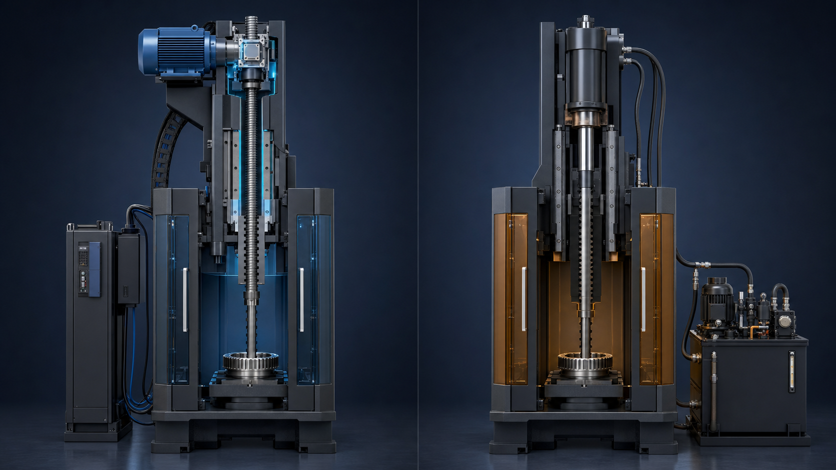
Conceptual illustration of an engineering team comparing two broaching-machine proposals. It is not a photograph of a BroachingMach installation and does not represent a dimensional machine design.
The short answer to servo vs hydraulic broaching machine is that neither drive is universally better. The correct choice depends on the workpiece, broach, force curve, stroke, duty cycle, motion requirements, controls, plant utilities, maintenance capability and lifecycle assumptions.
Start by defining what the supplier means by “servo.” An electromechanical servo cutting axis uses a servo motor and a mechanical transmission such as a screw. A servo-hydraulic system still uses hydraulic fluid and an actuator, but controls the pump or valve with servo technology. These are different architectures with different components and service requirements.
Then compare complete, application-sized proposals. Do not choose from a generic claim that servo is always more precise or efficient, or that hydraulic is always stronger or simpler.
Define the Drive Before Comparing the Machine
Conventional Hydraulic Main Drive
A conventional hydraulic cutting axis normally converts electric-motor power into hydraulic flow and pressure through a pump. Valves control fluid sent to one or more cylinders, and the cylinder creates the broaching motion.
See the BroachingMach hydraulic broaching machine range for examples of pull-up, pull-down and double-cylinder configurations. Those configuration names do not replace review of the actual hydraulic schematic and performance data.
Servo-Hydraulic Drive
“Servo-hydraulic” does not mean hydraulic-free. A servo motor may control pump speed, or a servo/proportional valve may control flow to a hydraulic cylinder. The system can offer more programmable control than a basic fixed-speed hydraulic package, but it still has hydraulic fluid, seals, filters, hoses or tubes, valves and an actuator.
This category matters because a quotation labelled “servo” may still require hydraulic maintenance and fluid-temperature management. Ask the supplier to identify the power path for the main cutting axis, return motion, clamping, tool handling and auxiliaries.
Electromechanical Servo Drive
An electromechanical servo cutting axis uses a servo motor, drive and feedback system with a screw, roller screw, gearbox or another mechanical transmission. It does not use a hydraulic cylinder for that cutting axis.
However, the machine may still contain hydraulic or pneumatic clamping, lubrication, coolant, doors or tool-handling functions. “Electric main drive” is not the same as “no fluids anywhere in the machine.”
Drive Type Is Not Orientation, Tool Motion or CNC
These labels describe different design dimensions:
- Hydraulic, servo-hydraulic and electromechanical servo describe how the main cutting motion is powered and controlled.
- Vertical and horizontal describe machine orientation and factory layout.
- Pull-up, pull-down, push and table-up describe how the tool or workpiece moves and how the load is carried.
- CNC describes the control and programmable-function architecture.
A vertical machine can be hydraulic or electromechanical. A CNC machine can use hydraulic actuators. A servo machine can be vertical or horizontal. A pull-down arrangement does not reveal the drive.
The existing guide to horizontal vs vertical broaching machines explains the layout question. Treat that as a separate decision from the drive comparison, then combine both decisions in the final specification.
Three Broaching Drive Architectures
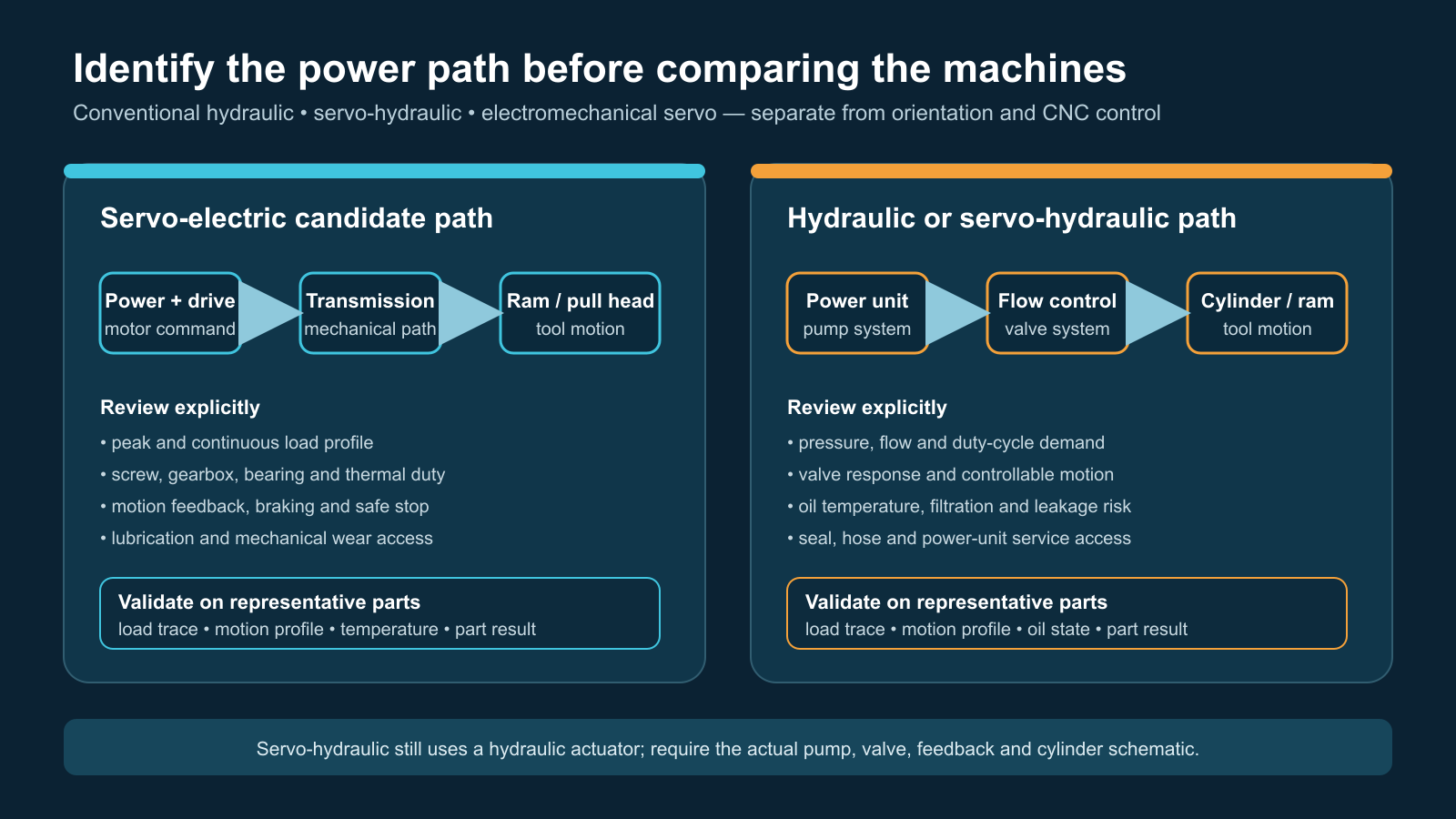
Conceptual system-boundary diagram. Actual machines may use different pumps, valves, transmissions, feedback devices and auxiliary systems; confirm the supplier's schematic.
| Evaluation area | Conventional hydraulic | Servo-hydraulic | Electromechanical servo |
|---|---|---|---|
| Main power path | Motor, pump, fluid, valve and cylinder | Servo-controlled pump and/or valve with hydraulic actuator | Servo motor and mechanical transmission |
| Motion programming | Depends on valves, feedback and control design | Often more configurable than a basic hydraulic circuit | Typically integrated with servo-drive and CNC recipes |
| Stored-energy issues | Hydraulic pressure and moving mass | Hydraulic pressure plus servo control | Electrical energy, gravity/moving mass and mechanical transmission |
| Maintenance focus | Fluid, filtration, leaks, seals, pump, valves and cylinders | Hydraulic components plus servo pump/valve, feedback and tuning | Motor, drive, feedback, screw/gearbox, bearings, guides and lubrication |
| Thermal behavior | Must be evaluated from pump duty, losses, reservoir and cooling | Must be evaluated from real control strategy and cycle | Must be evaluated from motor, drive, transmission and cycle |
| Best evidence | Hydraulic schematic and measured cycle data | Hydraulic/control schematic and measured cycle data | Drive/transmission data and measured cycle data |
This table defines what to investigate. It does not assign a universal winner.
Validate Force, Stroke and Duty Cycle First
Broaching force changes as teeth enter and leave the workpiece, chip load changes and friction or tool condition varies. A useful quotation should show how the proposed drive handles the required force over the complete cutting stroke.
Provide the supplier with:
- Workpiece drawing, material and heat-treatment condition
- Feature profile, starting condition and required finish
- Proposed broach drawing or enough data to design it
- Estimated or tested force curve, including appropriate engineering margin
- Cutting stroke, return stroke and clearance
- Required cutting-speed range and any speed changes within the stroke
- Parts per cycle, cycles per hour and planned shifts
- Tool loading, retriever and changeover requirements
- Abnormal-load detection and safe-stop requirements
Hydraulic systems can be engineered for demanding force and stroke combinations. Electromechanical systems can also be engineered for significant loads, but the selected motor, drive, screw or transmission, bearings, cooling and structural load path must fit the real cycle. Do not infer capability from the drive label.
The BroachingMach machine overview can help identify candidate layouts, but final sizing must come from the application package.
Compare Motion Control and Process Visibility
Some applications need only a stable cutting speed and defined end positions. Others need recipe changes, controlled acceleration, multiple speed zones, synchronized axes or production-data integration.
An electromechanical servo proposal may provide direct position and motor-load feedback through the drive. A servo-hydraulic proposal may provide comparable programmable functions through pressure, position and flow feedback. A conventional hydraulic design may also include closed-loop control. The implementation, sampling, calibration and software matter more than the marketing category.
Ask each supplier to demonstrate:
- How cutting speed is commanded and verified
- How position is measured
- Which load or pressure signals are recorded
- What trend data is retained for each cycle or batch
- How recipes are protected and changed
- How overload, tool jam and feedback loss are handled
- Whether data can be exported to the plant's required system
- What happens after a power interruption or emergency stop
“CNC controlled” is not a complete answer. Request the axis list, feedback devices, alarm logic, recipe fields and data interface.
Evaluate Energy and Heat With a Real Cycle
Energy claims are easily distorted when suppliers use different boundaries. One quote may count only the main cutting motor while another includes pumps, cooling, clamping, chip handling and idle time.
Give both suppliers the same reference cycle:
- Part loading and clamping
- Tool engagement
- Cutting stroke with the expected force profile
- Return and tool handling
- Chip/coolant functions
- Unloading
- Expected idle and standby periods
Request input power or energy for the complete machine over that cycle, plus heat rejected to the room or cooling circuit. State the operating schedule and local utility tariff. If regeneration is offered, ask where recovered energy goes and under what cycle conditions it is available.
An electromechanical drive can avoid continuous operation of a conventional hydraulic power unit, but that does not guarantee a fixed saving. A variable-speed hydraulic design can behave differently from an older fixed-speed system. Only comparable measured or calculated cycle data supports a decision.
Compare Maintenance and Serviceability
Eliminating a hydraulic main cutting axis removes its reservoir, fluid circuit, valves and cylinder from that axis. It adds or emphasizes different components: servo drive, motor, feedback devices, mechanical transmission, bearings and lubrication.
A hydraulic machine requires disciplined fluid condition, filtration, leak control, seal care and temperature management. The BroachingMach hydraulic broaching guide and guide to common hydraulic failures describe those system-specific concerns.
An electromechanical machine is not maintenance-free. Its screw or transmission has load, lubrication, alignment and life limits. Drive parameters and control backups also need management.
For each proposal, request:
- Preventive-maintenance schedule and task ownership
- Lubricants, filters, fluids and other consumables
- Expected inspection and replacement items
- Diagnostic procedure for load, position and motion faults
- Critical spare-parts list, price and lead time
- Local service coverage and remote-support method
- Training for operators, maintenance and controls personnel
- Safe method for supporting the moving assembly during service
The relevant question is not “which has less maintenance?” It is “which maintenance workload can the plant execute, and what downtime risk remains?”
Review Layout, Utilities, Automation and Safety
Compare certified general-arrangement drawings at the same application capacity. Include the frame, guarding, chip conveyor, reservoir, loading height, maintenance access, tool-change clearance, lifting points and any pit, platform or foundation requirement.
Also list every utility:
- Electrical service and peak demand
- Cooling water or chiller, if required
- Compressed air
- Hydraulic fluid and coolant
- Ventilation or mist extraction
- Network and production-data connection
- Floor loading and foundation
Safety must be evaluated from the completed machine risk assessment. Hydraulic systems can contain stored pressure; vertical electromechanical axes can contain gravity and mechanical stored energy. Both need verified guarding, interlocks, emergency stopping, lockout/tagout and safe maintenance support.
Do Not Let the Drive Promise Part Quality
Part accuracy, surface condition and broach life depend on the whole process:
- Broach design, manufacture, sharpening and coating
- Workpiece material, hardness and prior machining
- Cutting speed and cutting fluid
- Tool guidance and pull-head condition
- Fixture location, support and load path
- Machine rigidity, alignment and thermal state
- Chip evacuation
- Inspection method and sampling
A drive with well-controlled motion cannot correct an unsuitable broach, weak fixture or misaligned load path. Include the broach-tool range in the technical review and require a process plan, acceptance part and agreed inspection method.
Build a Comparable Lifecycle-Cost Model
Use the same horizon, production schedule and financial assumptions for both quotes. Include:
| Cost group | What to request |
|---|---|
| Acquisition | Machine, tooling, fixture, guarding, controls and options |
| Installation | Freight, foundation, utilities, lifting and commissioning |
| Production | Cycle capacity based on the agreed workpiece and tool |
| Energy | Complete-machine reference-cycle data and local tariff |
| Consumables | Fluid, filters, lubrication, coolant and disposal |
| Maintenance | Scheduled labor, service, spares and diagnostic tools |
| Downtime | Response time, critical spares and recovery plan |
| Changeover | Tool, fixture, recipe, verification and first-piece time |
| End of term | Major overhaul assumptions and residual value |
Do not accept a payback result unless the baseline and every included cost are visible.
A Practical Selection Workflow
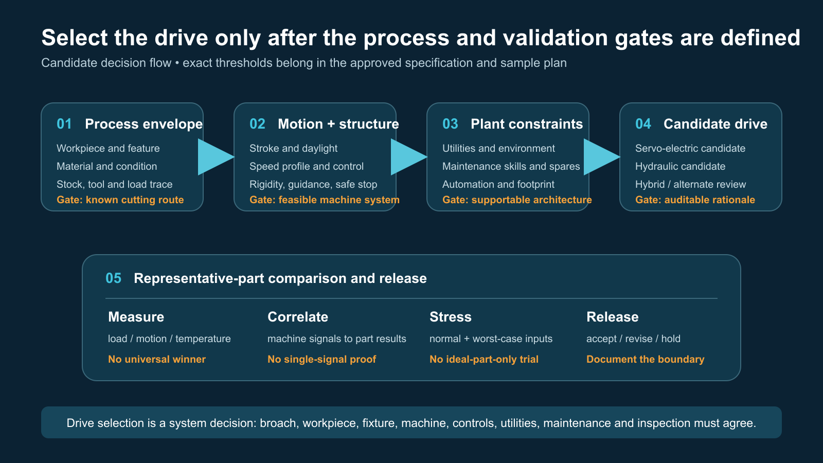
Selection workflow for preparing comparable proposals. It does not replace supplier engineering, machine risk assessment, tryout or acceptance testing.
- Freeze the application package. Define the part, material, profile, tool concept, force curve, stroke, speed and production schedule.
- Allow multiple architectures. Ask for conventional hydraulic, servo-hydraulic or electromechanical proposals where technically appropriate.
- Normalize the quotations. Require the same scope, auxiliaries, automation, acceptance test and lifecycle horizon.
- Review the load path. Check how tool, workpiece, table, frame and actuator carry peak force.
- Validate the cycle. Review motion, load, thermal behavior, energy boundary and abnormal-event response.
- Review service risk. Confirm maintenance tasks, skills, spares, support and safe access.
- Run a part trial. Use representative material and a production-intent broach where possible.
- Accept against evidence. Measure parts, cycle behavior, alarms and agreed machine data.
BroachingMach Examples
BroachingMach lists both servo broaching machines and hydraulic models. Its published CNC Double Servo Internal Broaching Machine is described as a CNC-controlled, screw-driven electromechanical system for internal teeth, splines and inner-hole parts.

BroachingMach CNC Double Servo Internal Broaching Machine. This real product image shows one electromechanical servo architecture; it does not represent every servo, servo-hydraulic or hydraulic machine.
For comparison, the company also publishes a hydraulic double-cylinder pull-down internal broaching machine. Suitability of either product family requires review of the actual part, broach, force, stroke, production and plant requirements.
Orientation remains a separate choice. Review the vertical broaching machine range and horizontal broaching machine range only after defining the workpiece, tool path and handling plan.
RFQ Checklist
Send these items with the inquiry:
- 2D drawing and 3D model
- Material standard, hardness and heat-treatment route
- Starting bore or surface condition
- Feature tolerances, surface requirements and inspection method
- Annual volume, batch size, shifts and target cycle
- Broach drawing, current process or sample part
- Force data, if available
- Required stroke, speed range and loading height
- Manual, robot or line loading
- Part-family and changeover requirements
- Available floor space, utilities and foundation limits
- Required CNC, traceability and network functions
- Local safety and compliance requirements
- Maintenance skills, preferred components and spare-parts policy
- Factory-acceptance and site-acceptance criteria
With this information, suppliers can compare architectures on the same engineering basis.
Frequently Asked Questions
Is a servo broaching machine always electromechanical?
No. “Servo” may describe an electromechanical cutting axis, a servo-controlled hydraulic pump or valve, or only one axis in a mixed machine. Ask for the main-axis power path and schematics.
Is a servo broaching machine always more accurate?
No universal conclusion is valid. Feedback and programmable motion can support process control, but part results also depend on tool, fixture, alignment, structure, material, cutting conditions and inspection.
Is a hydraulic broaching machine always better for high force?
Hydraulics are a valid way to produce high linear force, but the correct choice still depends on force over stroke, duty cycle, speed, structure, cooling and the complete quoted design. Compare application-sized proposals.
Does CNC mean the machine uses a servo main drive?
No. CNC describes control. A CNC machine may control hydraulic, servo-hydraulic or electromechanical actuators.
Which drive uses less energy?
It depends on the architecture and production cycle. Compare complete-machine energy for the same cutting cycle, auxiliaries, idle periods and cooling boundary. Do not use a generic percentage.
Which drive requires less maintenance?
They require different maintenance. Hydraulic systems emphasize fluid, filtration, seals, pumps, valves and cylinders. Electromechanical systems emphasize drives, motors, feedback, transmissions, bearings, guides and lubrication. Compare the supplier schedules and plant capability.
Can one machine combine electric and hydraulic systems?
Yes. The cutting axis may be electromechanical while clamping or tool handling uses hydraulics or pneumatics. Review every axis and auxiliary function.
What should decide the purchase?
The strongest evidence is an application-sized proposal supported by a clear force/stroke review, representative part trial, acceptance plan, service assessment and comparable lifecycle-cost model.


