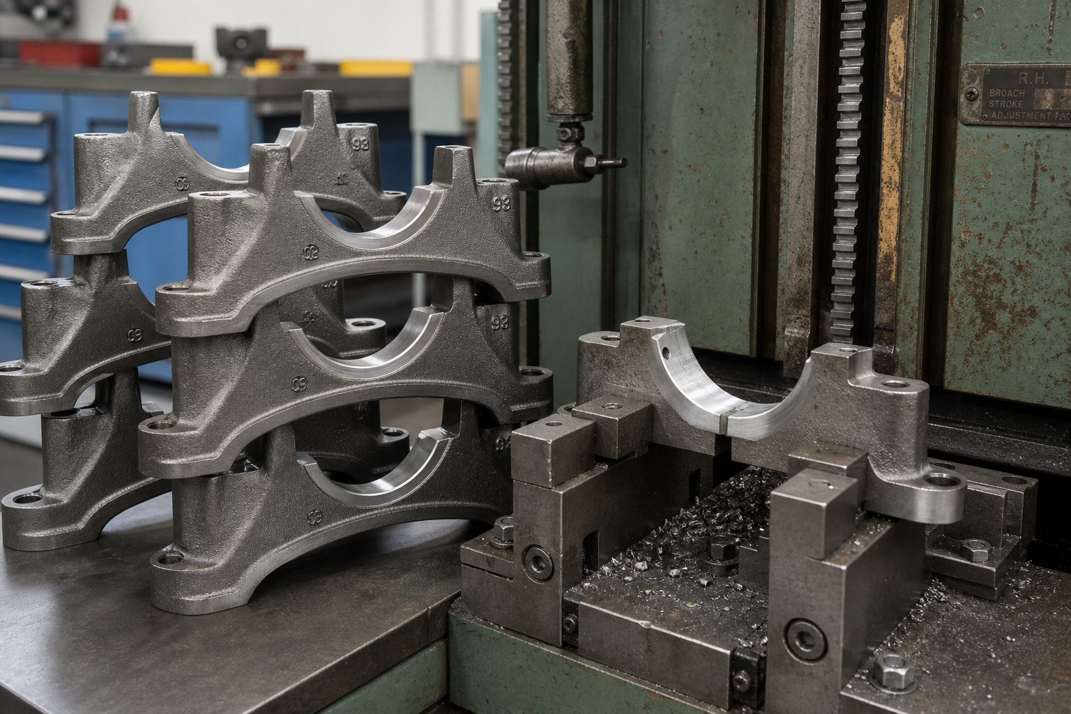
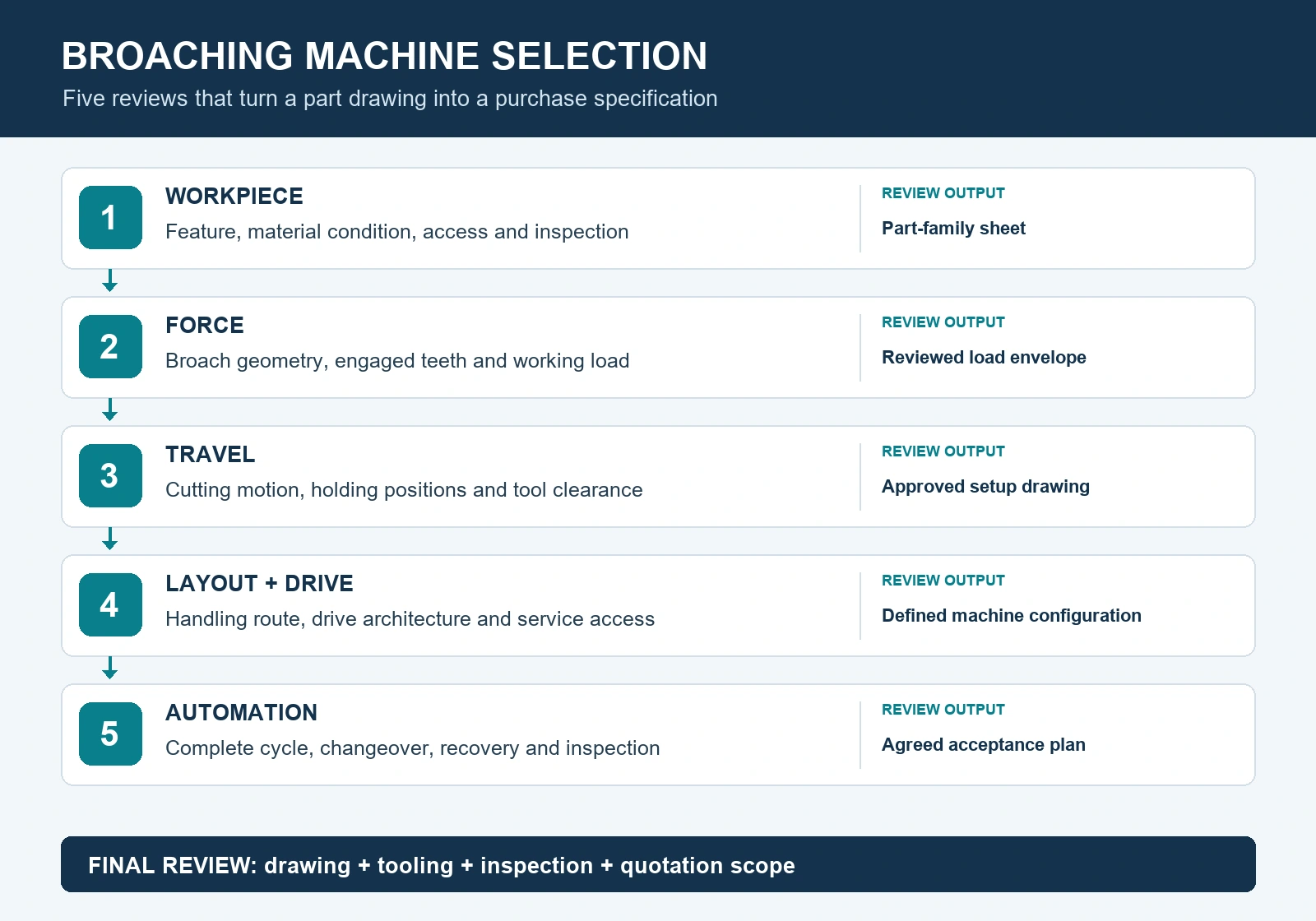
A broaching machine quotation should explain how the proposed equipment will produce your part, from the first cut to final inspection. To choose the right broaching machine, start with the finished feature and material condition, develop the broach concept, and confirm force and working travel before comparing layouts, drives and automation. This five-step guide helps you turn those decisions into a specification that suppliers can quote against, with clear responsibilities for tooling, handling and acceptance.
Table of Contents
- How to Choose the Right Broaching Machine
- Step 1: Define the Workpiece and the Broaching Method
- Step 2: Specify Broaching Machine Tonnage From the Tool
- Step 3: Check Broaching Stroke Length and Tool Clearance
- Step 4: Compare Layout and Servo vs Hydraulic Broaching
- Step 5: Define Automation and Acceptance Conditions
- Compare Quotations, Tooling and Long-Term Support
- Frequently Asked Questions
- Turn the Selection Into a Machine Specification
- References
How to Choose the Right Broaching Machine
This guide is for manufacturing engineers and buyers specifying linear broaching equipment for internal profiles, keyways and external surfaces. In linear broaching, progressively sized cutting teeth generate the feature as the tool or workpiece travels. The Open University's Multipoint cutting (translational) overview describes broaching as a vertical or horizontal process in which a shaped tool is pushed or pulled through the work.
Key takeaways
- Make the part drawing and proposed broach a shared input to machine selection.
- Confirm rated force at the working member and usable travel for the proposed setup.
- Compare complete production cycles, including handling, inspection and tool service.
Step 1: Define the Workpiece and the Broaching Method
Begin with a controlled drawing, material specification and description of the condition in which the part enters the operation. Include the starting hole or surface, stock allowance, heat-treatment stage, datum scheme and finished-feature requirements. Separate the hardest material condition from the largest feature: they may belong to different parts in the proposed workload.
Identify whether the tool can pass through the work. A through spline, a blind internal feature and an external slot present different access problems. Do not assume that a machine described as suitable for internal broaching also solves a blind feature. Mark the available tool entry, exit and chip space on the drawing before asking for a machine recommendation.
Tolerance and surface finish deserve separate entries in the specification. The Open University's Multipoint cutting (translational) overview gives a typical broached finish of 0.5–2.5 µm Ra, a possible low value of 0.25 µm Ra, and typical tolerances of ±0.01 mm. These are general process examples; a purchase specification should use the drawing's actual limits and define how the proposed part will be inspected.
Tooling can also change the appropriate production method. Pilot Precision Products' Keyway Broaching guidance distinguishes broach sets supplied with bushings and shims from one-pass tools that use a suitable bushing without shimming. A buyer should therefore identify the intended tool arrangement before comparing a hand-loaded setup with a production machine. See our keyway broaching machine guide for the machine-family context.
The output of this step should be a part-family sheet. Group parts by feature, access, material state and locating method, then identify the limiting member of each group. Ask bidders to flag any part that needs a different broach, fixture or machine arrangement instead of assuming that an entire family is covered by the headline capacity.
Step 2: Specify Broaching Machine Tonnage From the Tool
Broaching machine tonnage is a force rating. For an initial review, ask the tool designer to identify the material-removal area of each cutting tooth and the teeth engaged at each position. The evaluation needs the highest combined cutting load encountered during the stroke, together with the tool's own allowable load and the workholding reaction.
Rise per tooth is the increase in cutting height between successive teeth. Pitch is their spacing. Utku Köktürk's Sabanci University thesis, Optimization of broaching tool design, relates tooth rise to uncut chip thickness and describes its effect on cutting force. Consequently, applying a single chip thickness to every tooth can misrepresent a tool whose geometry changes along its length.
Arash Ebrahimi Araghizad's Sabanci University thesis, Geometrical optimization of the broaching tools by leveling of the cutting forces, examines tool generation under prescribed force constraints. Its simulations include limiting roughing and semi-finishing forces of 20,000 N, 10,000 N and 2,000 N. Under those simulated conditions, lowering the force limit reduces the permitted chip thickness and increases the number of teeth. The values are simulation inputs for the studied profiles, rather than machine sizes recommended for a general keyway.
This relationship makes the tool proposal important during quotation review. If a bidder recommends a smaller machine by changing the tooth layout, ask for the accompanying tool drawing, calculated load envelope and required travel. Review the revised cutting arrangement as a package instead of accepting a lower force rating on its own.
Before approving a force class, request these clarifications:
- Where is rated force specified: at the ram, puller, cylinder or another point?
- At what working speed and duty is that force available?
- What allowance is included for the agreed material variation and tool condition?
- What force limits protect the broach, pull end and fixture?
- How will the cutting-force estimate be checked during acceptance?
If a supplier starts with motor power or hydraulic pressure, ask it to show the connection to usable cutting force. Keep efficiency assumptions attached to that calculation; do not apply another blanket reduction to a rating already defined at the puller. Our broaching machine tonnage guide provides further calculation context.
Step 3: Check Broaching Stroke Length and Tool Clearance
Broaching stroke length is the available working travel of the moving member. Tool overall length, cutting-section length and workpiece length describe different dimensions. Put them on the same setup drawing, together with the puller, fixture, support and required exit position, to establish whether the proposed movement completes the operation.
In Optimization of broaching tool design, Utku Köktürk of Sabanci University explains that tooth pitch affects both the number of teeth in the cut and tool length. Chips occupy the gullets between teeth until they leave the workpiece. This links the space needed for chip accommodation to the tool design; a longer cut cannot be assessed from workpiece length alone.
Ask for a motion sequence showing the tool's starting position, first engagement, completion of the finishing section, release and return. On a machine with a moving work table or a tool-transfer arrangement, review the relative movement of tool and workpiece. A statement that the ram has enough nominal stroke does not settle the entire loading and transfer sequence.
Use separate checks for:
| Check | What to show on the supplier drawing |
|---|---|
| Cutting travel | Position where the finishing teeth clear the required feature |
| Holding arrangement | Pull-end engagement, fixture thickness and locating surfaces |
| Tool support | Support locations throughout loading, cutting and return |
| Handling clearance | Space to insert, remove and service the proposed broach |
| Building envelope | Full-travel positions, maintenance access and lifting route |
Review the assembled machine and tooling arrangement before choosing orientation. A horizontal layout may solve a handling problem while using more floor length; a vertical layout needs its working and service positions checked against the building. Compare those drawings directly using our horizontal versus vertical broaching machine guide.
Step 4: Compare Layout and Servo vs Hydraulic Broaching
Layout and drive are separate decisions. First compare how parts are located, loaded and supported in the proposed vertical or horizontal arrangement. Then examine the equipment that generates and controls the cutting motion. The phrase servo vs hydraulic broaching is incomplete unless the bidder identifies whether it proposes an electromechanical drive, conventional hydraulics or a servo-hydraulic system.
Bosch Rexroth's Efficient linear drive for tire production describes a servo-hydraulic architecture combining a servo drive, hydraulic pump, cylinder and fluid circuit. Its maintenance description still includes fluid sampling and refilling. This is a useful architectural example when evaluating a proposal that uses the word servo: servo control does not by itself establish that the machine has no hydraulic equipment.
For each quotation, request a drive schematic or clear component description. Ask how cutting speed is controlled under load, how the working member is guided, and what feedback is used for position or force. If force monitoring is offered, define the signal, alarm response and record available to the operator. Avoid treating the presence of a sensor as a complete process-monitoring system.
| Proposal description | Questions that make it comparable |
|---|---|
| Conventional hydraulic | How are flow, pressure and oil temperature controlled during production? |
| Servo-hydraulic | Which pump, valves, sensors and fluid-service tasks remain in the system? |
| Electromechanical servo | What mechanism transmits force, and what are its load, lubrication and duty requirements? |
| Any architecture | What result is demonstrated on the agreed workpiece and complete production cycle? |
For energy comparisons, specify the same workload, handling arrangement and measurement boundary. Request the stated operating conditions behind an estimate or demonstration rather than comparing motor nameplates. Also review maintenance access with the proposed enclosure in place. Our servo versus hydraulic broaching comparison explores the terminology in more detail.
Step 5: Define Automation and Acceptance Conditions
Separate the cutting operation from the complete production cycle. The Open University's process overview describes roughing and finishing within a single pass; loading, locating, clamping, tool return, unloading and inspection must also fit the proposed cycle. Ask bidders to describe each action and identify any operator task included in their timing.
Use the actual part family when discussing automation. Ask how a part is oriented, how a wrong or incomplete load is detected, and how finished parts are separated from incoming stock. For mixed production, request a changeover demonstration covering the fixture, tool, program, gauges and first-part verification. Record which changes require maintenance staff and which an operator can perform.
Define the trial before the equipment order. Supply agreed drawings and material-condition information, specify the tool condition for the demonstration, and identify who provides representative blanks. Establish the inspection method for size, profile, position, surface finish and burr condition where the drawing calls for them. Agree how nonconforming results will be recorded and resolved.
The acceptance plan should also describe interrupted-cycle recovery. Ask the supplier to demonstrate its approved response to a partially completed cycle, a monitoring alarm and a handling fault. Include operator training and documentation for those situations. Confirm responsibilities for the machine's risk assessment, guarding and safe intervention procedures with the parties responsible for the installation.
For unattended operation, ask what records connect a finished part or batch to the machine program, tool identification and inspection result. Specify the required interface to the surrounding line before ordering the loader. A standalone cycle demonstration should be supplemented by the agreed integration checks when adjacent equipment is part of the purchase scope.
Compare Quotations, Tooling and Long-Term Support
Compare a complete production scope before comparing prices. Pilot Precision Products' distinction between conventional keyway sets and one-pass tools shows why a label such as “keyway broaching package” leaves important details unresolved. Require each quotation to identify the supplied broach, bushings or guides, shims where applicable, workholding and gauges.
Use the following commercial schedule to make exclusions visible:
| Cost or responsibility | Required quotation entry |
|---|---|
| Machine and handling | Included equipment, interfaces and customer-supplied items |
| Tool package | Tool drawing approval, initial tools and replacement arrangements |
| Tool service | Sharpening route, transport, inspection and return-to-production responsibility |
| Installation | Foundation information, utilities, rigging and commissioning scope |
| Acceptance | Trial parts, gauges, attendance and resolution of deviations |
| Continuing support | Documentation, training, spare parts and support contact |
For used equipment, ask for evidence of condition and compatibility with the proposed job. Request inspection of guides, working motion, clamping, controls and the supplied documentation. Include the expected refurbishment and tooling work in the comparison. If a seller cannot demonstrate the required setup, identify that uncertainty explicitly before committing to the purchase.
For new equipment, specify the deliverables that survive commissioning: approved drawings, component information, software backups where supplied, maintenance instructions and the final acceptance record. Ask how a replacement broach will be specified after the original needs service. A clear service arrangement is especially important when the machine, tool and automation come from different parties.
Frequently Asked Questions
What if the part drawing changes after the machine is ordered?
Treat the revision as a change requiring review by the machine, tool and fixture suppliers. Identify the affected features and request written confirmation of compatibility, delivery impact and any new acceptance conditions. Keep the approved revision attached to the order so that trial parts and inspection use the same drawing.
What should an RFQ say about broach resharpening?
Ask who inspects and sharpens the tool, how its condition is documented, and what checks are required before production resumes. Request identification of any associated setup adjustments. Include responsibility for transport and replacement tooling so that the service plan can be evaluated alongside the equipment proposal.
Can a supplier quote before the production volume is settled?
Yes. Provide the available volume forecast and ask for clearly separated handling options, staffing assumptions and changeover arrangements. Keep uncertain demand visible in the quotation comparison. This allows the purchasing team to evaluate the commitment attached to each configuration without presenting a forecast as an established production requirement.
Turn the Selection Into a Machine Specification
To choose the right broaching machine, turn the engineering review into an agreed purchase specification. Attach the part-family sheet, tool and setup drawings, force and travel requirements, handling sequence, inspection plan and quotation exclusions. Assign responsibility for each unresolved interface before approving the order.
The practical next step is a review of your drawings and production requirements. Contact UBright Solutions with the feature drawings, material condition, intended part mix and available building layout to discuss the machine and tooling proposal for your application.
References
- Multipoint cutting (translational) — The Open University — Provides the attributed general examples of broached surface finish and tolerance.
- Keyway Broaching — Pilot Precision Products — Distinguishes keyway broach sets, bushings, shims and one-pass tooling.
- Geometrical optimization of the broaching tools by leveling of the cutting forces — Sabanci University — Links to Arash Ebrahimi Araghizad's thesis and its simulations of tool design under force constraints.
- Optimization of broaching tool design — Sabanci University — Links to Utku Köktürk's thesis on pitch, gullet space and machine-tool-part constraints.
- Efficient linear drive for tire production — Bosch Rexroth — Identifies the hydraulic components and fluid-service requirements of a servo-hydraulic drive architecture.