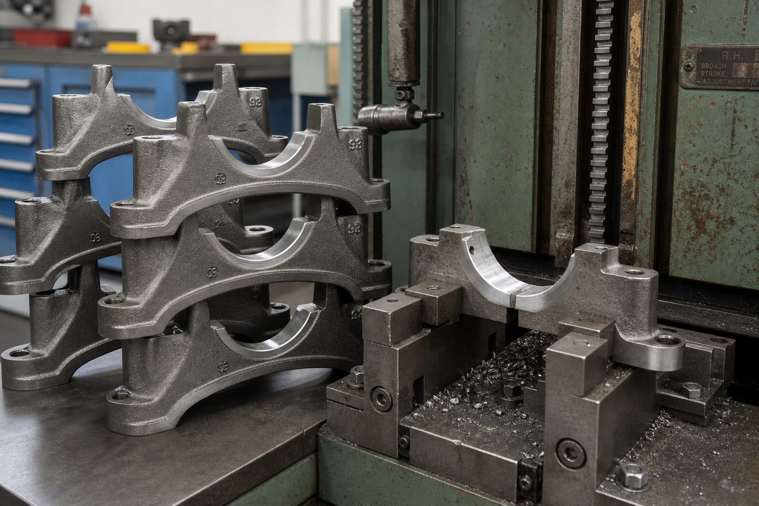
If you machine keyways, splines, hex sockets or other precision internal forms at production volumes, this guide is for you. It walks through hydraulic broaching the way a real project runs — what the process can cut, what the tool holds, what the hydraulic drive adds, how to run the machine safely and keep its oil clean — so you can move from a part drawing to a machine and tooling decision with sources behind every number.
Table of Contents
- What Hydraulic Broaching Is and How It Cuts
- Broach Tool Anatomy: Roughing, Semi-Finishing and Finishing Teeth
- Precision and Surface Finish You Can Specify
- What a Hydraulic Broaching Machine Adds to the Cut
- Internal Broaching and Surface Broaching Applications
- Setting Up and Running a Broach Safely
- Coolant, Chips and Hydraulic Oil Cleanliness
- Broaching Questions We Get from Buyers
- Plan Your Broaching Project
- References
Hydraulic broaching finishes a keyway, spline, hex socket or fir-tree slot in one stroke: a multi-tooth broach is pulled or pushed through a pre-machined hole, or across an external surface, and every tooth takes its share of the stock on the way. On a hydraulic broaching machine the ram is driven by a hydraulic cylinder rather than a servo ballscrew or a mechanical crank, which keeps the cutting stroke steady at the low speeds broaching runs at. That combination — single-pass form generation plus smooth hydraulic power — is why the process still anchors high-volume production of gears, connecting rods, turbine discs and tool sockets.
This guide covers what actually happens inside the cut: how a broach is built, what precision and surface finish you can put on a drawing, what the hydraulic drive adds, where internal and surface work apply, and how to run and maintain the machine so both the tool and the oil survive. Figures quoted throughout are traceable to the sources listed in the References.
What Hydraulic Broaching Is and How It Cuts
Broaching is best understood as shaping with a whole rack of tools welded into one bar. The Cutting Tool Applications handbook chapter published by American Machinist defines the tool plainly: "A broach is a long multi-tooth cutting tool with successively deeper cuts," and "each tooth removes a predetermined amount of material in a predetermined location." Nothing about the chip thickness is decided by the machine or the operator at cut time; the tooth heights decide it in advance.
That is also why one stroke is enough. The same chapter describes "rough, semi-finish and finish cutting teeth combined in one tool or string of tools," and notes that "a broach tool frequently can finish machine a rough surface in a single stroke." Özkan Öztürk's 2003 thesis at Sabancı University puts the productivity consequence directly: "Roughing, semi-finishing and finishing can be performed in one stroke of the tool increasing productivity and reducing set-up time," and "high quality surface finish can be obtained due to straight motion of the tool" — there is no corner-turning, no interpolation, just one straight pass.
The same rigidity cuts the other way. Broaching gives up flexibility that other processes keep: "all process parameters, except cutting speed, are built into broaching tools," Öztürk writes, so "it is not possible to modify cutting conditions during the process once the tool is manufactured." The feed, the depth per tooth and the final size are tool-design decisions made before the broach is ever ground.
Two geometric requirements frame every broaching job. Internal broaching "requires a starting hole or opening in the workpiece so the broaching tool can be inserted," as the handbook chapter puts it. And for any profile, "almost any irregular cross-section can be broached as long as all surfaces of the section remain parallel to the direction of broach travel." Blind pockets and undercut forms that a mill can reach are off the menu for a straight pull.
Economically, the tool is expensive and the stroke is cheap. "Broaching competes favorably with other processes, such as boring, milling, shaping and reaming. Although broaches tend to be expensive, the cost is justified because of their use for high-production runs."
Key takeaways
- A broach combines roughing, semi-finishing and finishing teeth in one tool; one stroke finishes the form.
- All process parameters except cutting speed are fixed in the tool, so broaching rewards high, stable volumes.
- Internal work needs a through starting hole; profiles must stay parallel to the stroke direction.
Broach Tool Anatomy: Roughing, Semi-Finishing and Finishing Teeth
Along its length a broach is divided into working zones, and the Cutting Tool Applications chapter maps them: "the roughing teeth, semi-finishing teeth and finishing teeth. The first roughing tooth is proportionately the smallest tooth on the tool. The subsequent teeth progressively increase in size up to and including the first finishing tooth." The step between adjacent teeth — the tooth rise — "is usually greater along the roughing section and less along the semi-finishing section. All finishing teeth are the same size."
The finishing zone hides more engineering than its uniform appearance suggests. Öztürk's thesis explains that "roughing teeth are suscept to higher chip load than finishing teeth," and that because grinding broach teeth is difficult, "some teeth have equal height in finishing section in case teeth wear. The teeth start to wear from the first teeth to the last." The last teeth of all are insurance: "there are teeth with no rise which remove the left over material due to worn teeth" — dead-size teeth that only clean up what worn cutting teeth left behind.
Pitch, the tooth spacing, is a stability decision. "Pitch is calculated so that, preferably, two or more teeth cut simultaneously. This prevents the tool from drifting or chattering," the handbook chapter states. Below each tooth sits a gullet shaped so "chips curl tightly within themselves, occupying as little space as possible." On round and hole-shaping broaches, chip control becomes critical enough to add chipbreakers — notches ground into the roughing and semi-finishing teeth, "staggered so that one set of chipbreakers is followed by a cutting edge." Without them the tool would machine "ring-shaped chips that would wedge into the tooth gullets and eventually cause the tool to break."
Alignment is carried by the pilots. The front pilot "assures correct axial alignment of the tool with the starting hole, and serves as a check on the starting hole size"; the rear pilot keeps the tool true as the finish teeth exit the far side. Designers may also set teeth at a shear angle "to improve surface finish and reduce tool chatter." For long, expensive tools, shell construction splits the broach into sections so "worn sections can be removed and re-sharpened or replaced, at far less cost than a conventional single piece tool."
At the end of the tool chain, burnishers do no cutting at all: they are "broaching tools designed to polish rather than cut a hole," changing diameter by "no more than 0.0005 to 0.001 inches."
Tool steel choice follows the workpiece. The SK Broach Engineering Team's specifying guide grades the options: M2, at "63–65 HRC" hardness, suits "mild steel, medium carbon steel, aluminium, brass, and cast iron" up to roughly 30 HRC; M35 adds 5% cobalt for stainless and alloy steels that work-harden and heat the edge; ASP2030, a powder-metallurgy grade, is "the right choice when broaching hardened steels above 40 HRC, titanium alloys, Inconel, or any superalloy."
Precision and Surface Finish You Can Specify
Because every tooth position is ground into the tool, broaching is repeatable in a way few chip-making processes match. The SK Broach Engineering Team's guide states it as a shop-floor expectation: "A well-made HSS broach consistently holds IT7 to IT8." In ISO 286-1 terms, that is tolerance grades 7 and 8 on the linear size system the standard defines. Typical values from the same guide: keyway widths held to H7/H8, or ±0.010–0.020 mm; involute splines to DIN 5480 Class 7 or 8, with tooth thickness at ±0.010 mm; round internal bores to H6/H7, or ±0.005–0.015 mm, with H6 requiring a ground broach. Tighter is possible — "IT6 and below are achievable but require ground-finish broaches and more controlled machining conditions."
Surface finish scales with the tooth zone that produced it, which is why the last section of the broach gets the attention. The SK Broach guide's working numbers: a roughing broach leaves Ra 3.2–6.3 µm, semi-finishing Ra 1.6–3.2 µm, a finishing broach Ra 0.8–1.6 µm, and a ground finishing broach Ra 0.4–0.8 µm. The step up matters commercially: "For Ra 0.8 or better, a ground-tooth finishing broach is required — this affects the tooling cost and should be specified upfront rather than discovered at inspection." The same guide also explains why broached walls tend to beat milled ones: "the cutting action is smooth and continuous rather than intermittent."
The workpiece sets the ceiling, not the tool. MSC Industrial Supply's broach guide is blunt on the boundary: "Use materials with a hardness rating up to HRC 38 for the best results. Avoid broaching harder materials, as they can damage the tool." Above that line the process needs specialized tooling and machine arrangements rather than standard shop practice.
At the far end of the scale, Öztürk's thesis takes turbine disc work as its application case — "turbine disc broaching is considered as the application which is one of the most complex broaching operations" — machining fir-tree slots in superalloy discs, where geometry is complex and tolerances are "very tight."
What a Hydraulic Broaching Machine Adds to the Cut
The machine exists to move the broach through the work in a straight line at controlled speed, and the drive is a genuine design fork: "The type of drive, hydraulic or electromechanical, is another important factor in machine selection," as the Cutting Tool Applications chapter puts it. The layout statistics explain where you will meet each: "About 60 percent of the total numbers of broaching machines in existence are vertical," and those vertical machines "are almost all hydraulically driven." Horizontal internal work is overwhelmingly hydraulic too — "fully one-third of the broaching machines in existence are this type," hydraulically driven horizontal pull machines "built with pulling capacities ranging from 2 1/2 to 75 tons," with "strokes up to 120 inches" and "cutting speeds generally limited to less than 40 FPM."
Hydraulic drive suits broaching for a physical reason: the process wants high force at low, steady speed — exactly the corner where a cylinder with a metered oil flow excels and where a mechanical drive gets complicated. On horizontal surface machines, electromechanical drives win work through "their smooth ram motion and the resultant improvements in surface finish and part tolerances," at "cutting speeds, in some instances, of over 300 FPM" — speed that internal work rarely needs.
Within internal machines, layout decides how the part is located. Vertical pull-down machines "are capable of holding internal shapes to closer tolerances by means of locating fixtures on top of the worktable," with "pulling capacities of 2 to 75 tons" and speeds up to 80 FPM, while pull-up machines pass the broach up through a hole in the table so the part sits below. Our pull-up and pull-down internal broaching machines cover both layouts; the pull-up vs pull-down comparison walks through which fits which part families.
Under all of this sits the bed, and grey cast iron earns its place there. An IJRITCC paper on machine beds frames the requirement: "Damping reduces vibrations by dissipating the energy," and a bed must combine that damping with rigidity — grey iron Class 300 is listed for "heavy-duty machine tools, bed, presses, high pressure hydraulic parts." A broaching machine's long, force-loaded stroke is exactly the case that material answers.
Machine selection, finally, is tooling-led. The handbook chapter's ordering is worth quoting whole: "The type of broach cutting tool required for a given job is the single most important factor in determining the type of broaching machine to be used. Second in importance is the production requirement." For the drive decision itself — hydraulic versus servo — our servo vs hydraulic broaching machine comparison goes deeper, and the horizontal broaching machine guide covers layout and setup for the most common configuration.
Internal Broaching and Surface Broaching Applications
Internal broaching is the classical use: "Internal operations transform a round-drilled hole into any configuration, using either a push or a pull broach," in the words of MSC Industrial Supply's guide. The push/pull choice is a mechanics problem, not a preference. A push broach "must be relatively short since it is a column in compression and will buckle and break under too heavy a load," the handbook chapter warns; pull broaches, always machine-driven, are pulled "up, down or horizontally through or across the workpiece" and can be made long. MSC's guide adds the practical split: most applications use push broaches, but "pull broaches offer longer lengths of cut when broaching square and hexagon shapes."
Keyways remain the flagship internal job — "almost all keyways in machine tools and parts are cut by a keyway broach — a narrow, flat bar with cutting teeth spaced along one surface" — with internal keyways usually guided by "a slotted bushing or horn to fit the hole." Öztürk's thesis opens with the wider internal family: "Broaching is commonly used in industry for the machining of variety of external or internal features such as keyways, noncircular holes, fir-tree slots on turbine discs."
Surface broaching attacks the outside of the part. MSC's guide describes it as operations that "replace milling or shaping by producing precise dimensions at higher speeds. Typical examples include flats, notches, keyways, contoured surfaces, external gear teeth, and serrations." A special orbital variant, turn-broaching, machines crankshaft and camshaft journals in one sweep — our turn broaching guide covers that process on its own.
Across both families, volume decides adoption: where milling needs multiple passes and setups, a broach finishes the form in one stroke, which is why the process concentrates in automotive, agricultural equipment, hand tools and turbine manufacture. Our broaching machines overview groups the machine families by work type.
Setting Up and Running a Broach Safely
Most broaching accidents and most broken broaches trace back to setup, not to the cut itself. MSC Industrial Supply's operating tips concentrate on four protections:
- Alignment. "Align the tool correctly to prevent breakage or drift." A broach that starts tilted loads its teeth unevenly and can crack the shank.
- Engagement. "Always keep at least two teeth engaged during the cut and use bushings to support the broach and maintain accuracy." One tooth in cut means the tool can walk; two or more balance the side forces by design.
- Lubrication. "Apply proper lubrication to reduce friction and improve chip removal."
- Chip clearing. "After each pass, use a stiff brush to clear chips from the cutting section of the broach." Chips packed in a gullet are carried back through the finished hole on the next pass.
Respect the material boundary from the previous section — keep workpieces within the HRC 38 ceiling that standard broaches are built for. Beyond that, standard shop discipline applies: verify stroke limit stops before the first cut, clamp so the cutting force pushes the workpiece into the fixture, and never adjust speeds or stops mid-stroke.
Coolant, Chips and Hydraulic Oil Cleanliness
On a hydraulic broaching machine there are two fluids to manage, and the second is easy to neglect. Cutting coolant keeps friction down and flushes chips out of the gullets, whose spaces are sized around tightly curling chips; clear chips from the bed and tank routinely, because chips displaced into the tank take the place of coolant volume.
The hydraulic oil is the machine's bloodstream, and contamination is how hydraulic systems die early. Parker Hannifin's Guide to Contamination Standards explains the counting system used across the industry: the three figures of an ISO 4406 code "represent ISO level contamination grades for particles of >4µm(c), >6µm(c) and >14µm(c) respectively." The baseline number that surprises most shops: the typical cleanliness of "new hydraulic oil straight from the manufacturer" is 20/18/15 — new oil from the drum is not clean oil by system standards.
Targets depend on what the oil has to protect. Parker's table assigns 19/17/14 to "general machinery and mobile systems" with gear pumps, 18/16/13 to high-quality reliable systems, and 16/14/11 to "performance servo and high pressure long-life systems," down to 15/13/09 for silt-sensitive servo applications. Aerospace legacy standard NAS 1638 remains in wide industrial use alongside the ISO codes. Water matters too: by Parker's conversion, a reading of 250 PPM equates to "a quantity of absorbed water in a 400 litre capacity system of 0.1 litre" — a tenth of a litre of water doing pump and valve damage.
For the machine-side schedule — oil and filter changes, filter-net cleaning, seal and hose checks — follow the full broaching machine preventive maintenance checklist.
Broaching Questions We Get from Buyers
Should I choose a hydraulic or a servo broaching machine?
Both drives finish the same forms; the difference is in stroke control, energy behavior and maintenance profile at your volumes. The servo vs hydraulic comparison breaks the decision down by part family and duty cycle.
Pull-up or pull-down for internal work?
Pull-down locates the part on top of the table, which supports closer tolerances; pull-up drops the part below the table and suits round and irregular holes. The pull-up vs pull-down layout guide covers chip flow, floor space and fixturing.
Which machine family do I even need?
Start from the tooling, as this guide argues, then match production volume. The broaching machine overview and the horizontal broaching machine guide map the families to work types.
What usually goes wrong with a hydraulic broaching machine?
The recurring failures are oil-related: contamination, leaks and pump delivery loss. The common failures guide lists each failure with its causes and fixes.
Plan Your Broaching Project
Bring us the part drawing — profile, tolerance class, material and hardness, and expected volumes — and the tooling, machine layout and drive follow from it, as this guide has traced. If you are specifying a hydraulic broaching machine or a custom broach for keyways, splines or internal forms, contact our engineering team and we will match the machine family, pull direction and tooling grade to your production plan.
References
- Cutting Tool Applications, Chapter 14: Broaches and Broaching — American Machinist — George Schneider, American Machinist, 2020; process definition, tool anatomy, push/pull mechanics, machine types and drive data.
- Modeling of broaching for optimization purposes — Sabancı University Research Database — Özkan Öztürk, master's thesis, 2003; three-section tool structure, chip load, wear-compensating finishing teeth, one-stroke rationale, turbine disc application.
- How to Specify a Broach: Tolerances, Materials and Lead Times — SK Broach — SK Broach Engineering Team, 2026; tolerance classes, Ra values by broach stage, HSS grade selection.
- Broach Tool Types & Broaching Tips — MSC Industrial Supply — MSC Industrial Supply; material hardness limit, internal and external operations, setup and chip-handling tips.
- Guide to Contamination Standards — Parker Hannifin — Parker Hannifin; ISO 4406 cleanliness codes and targets, NAS 1638, water-in-oil conversion.
- Grey Cast iron The best suitable material for lathe machine bed — IJRITCC — Ajay Bhardwaj, IJRITCC, 2014; grey-iron damping rationale and Class 300 uses for machine beds.
- ISO 286-1:2010 Geometrical product specifications (GPS) — ISO code system for tolerances on linear sizes — Part 1 — ISO — International Organization for Standardization; defines the IT tolerance grade code system.