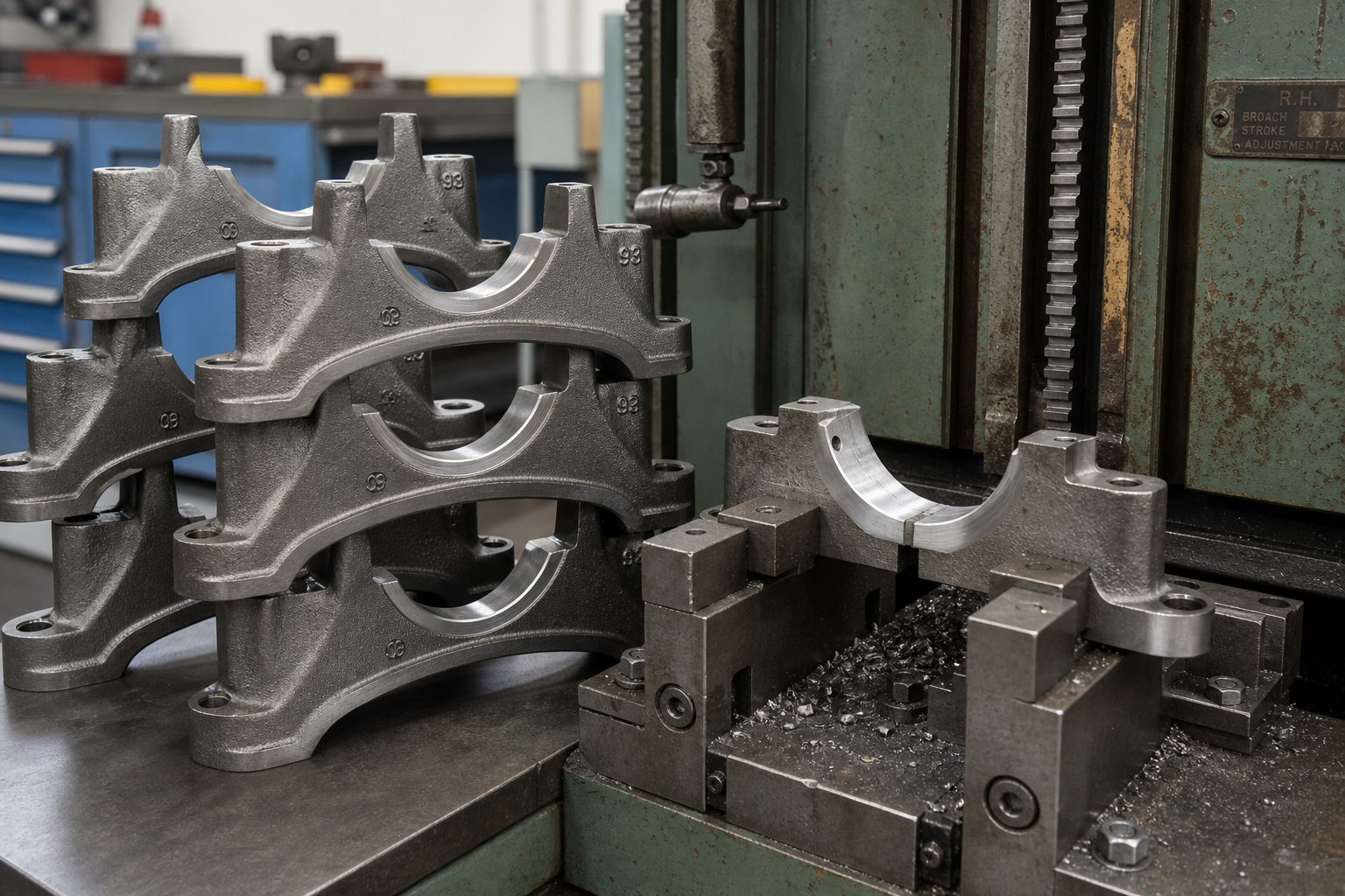
The common failures to investigate on a hydraulic broaching machine include delayed ram movement, external oil leakage, weak pulling force, loss of pump delivery, a sticking slide or ejector, and abnormal vibration. For operators and maintenance engineers, the useful starting point is the symptom and the conditions in which it appears. A fault that begins after an oil change needs a different investigation from one that develops only as the cut loads the machine.
Table of Contents
- Common Failures: Start With the Symptom
- Slow or Spongy Ram Stroke After an Oil Refill
- Oil Leaks: Inspect the Seal and Its Working Conditions
- Weak Pulling Force: Check Pressure Under Load
- Hydraulic Pump That Stops Delivering Oil
- Slide or Ejector Rod That Sticks or Fails to Return
- Broaching Machine Vibration: Separate Hydraulic and Tool Symptoms
- Preventive Checks and the Repair Record
- Get Help With a Persistent Broaching Fault
- References
Common Failures: Start With the Symptom
Record what changed before adjusting anything: the job, tool, oil service, motor work, or control sequence. Also note whether the symptom appears during approach, cutting, return, or idle running. This creates a repair record that the service engineer can use, rather than a list of parts already replaced.
Valmet's hydraulic power unit troubleshooting guide groups faults by lost delivery, low pressure, noise, leakage and heating. That symptom-based structure is useful for organizing a broaching-machine investigation. The machine manual and hydraulic schematic determine the actual test points and settings.
| Observation to record | Question for the investigation |
|---|---|
| Delay immediately after oil service | Was air introduced during filling or maintenance? |
| Fresh oil outside the circuit | Where does the leak begin, and under which movement? |
| Stalling as the broach engages | What pressure and flow are available under that load? |
| Motor running without actuator movement | Is the pump delivering, and is the control sequence enabled? |
| Ejector or slide stopping at a repeatable position | Is the command missing, or is movement mechanically restricted? |
| Vibration confined to cutting | Does inspection show a tooling or workholding problem? |
Treat these as investigation questions, not diagnoses. Similar symptoms can have different causes. A maintenance observation should identify the operating state and the location of the measurement, so that the next person can reproduce it.
Before opening the circuit or entering a movement zone, follow the machine's isolation procedure, release stored hydraulic energy and secure movable assemblies. Pressure testing and energized electrical checks belong to qualified personnel using the specified equipment. Do not loosen a pressurized fitting to investigate a leak or force an ejector back by hand.
Slow or Spongy Ram Stroke After an Oil Refill
The Lee Company explains that trapped air compresses before hydraulic fluid can initiate actuator movement. This can delay the response to a directional-valve command. When the command closes, the compressed pocket can expand and continue displacing fluid. The result may include hesitation or movement that continues after the expected stopping point.
An oil refill is therefore a useful clue, but it does not prove that air is the only cause. Compare the timing of the symptom with the service record. Note which lines were opened and whether the approved filling and commissioning procedure was completed. This is more informative than repeatedly changing valve settings in an attempt to make the stroke feel faster.
Use the machine manufacturer's bleeding procedure and designated service points. The Lee Company describes engineered bleed orifices and vent valves, including devices positioned where pockets can collect. Their geometry is a circuit-design matter; drilling an improvised bleed hole is not an appropriate field repair.
Vincent G. Magorien's article in Power & Motion distinguishes dissolved, entrained and free air. These terms describe different conditions, so the repair record should state what was observed: visible foam in the reservoir, bubbles at a suitable inspection point, or a delayed actuator response. A description such as an air problem alone loses useful detail.
After the approved intervention, verify the approach and return sequence before returning to cutting. If the response remains inconsistent, preserve that observation and continue the diagnosis. Do not treat a temporary improvement after a restart as confirmation that the underlying fault has been removed.
Oil Leaks: Inspect the Seal and Its Working Conditions
Seal manufacturer JSP identifies wear, extrusion, twisting, uneven wear, aging and assembly tolerances as possible failure mechanisms. Its discussion connects particles in oil and rough mating surfaces with seal wear, and describes how aged material can harden and lose elasticity. A replacement seal needs suitable working conditions as well as the correct part specification.
During disassembly, retain the failed seal for inspection and record where damage occurs. An uneven wear pattern raises a different question from a uniformly hardened seal. Check the mating surface and installation details against the component documentation. Do not decide that all leakage is caused by the same mechanism simply because it appears at a cylinder.
Daramco's troubleshooting guide for hydraulic bending machines associates leakage with seal wear, excessive oil temperature and overload. These are general hydraulic considerations to review on a broaching machine; its guide does not supply a seal selection or temperature limit for your machine.
For a practical repair handover, record the component location, when leakage occurs, the seal specification fitted and the inspection findings. A photograph of the failed part can help the service team. Clean the affected area using the approved procedure so that verification can distinguish fresh leakage from oil left over from the repair.
Check the result through the relevant movement sequence. If the leak returns, compare the new evidence with the original findings before fitting another seal. Repeated replacement without identifying the working condition can obscure the cause and adds avoidable downtime.
Weak Pulling Force: Check Pressure Under Load
A ram that moves during approach but stalls as the tool engages needs observations from the loaded part of the cycle. A pressure reading taken elsewhere or during idle running does not describe that same condition. Record the gauge location, operating phase and job alongside the reading.
Valmet lists a relief setting that is too low and internal leakage in worn pump parts among the causes of low hydraulic-system pressure. These are diagnostic possibilities. They do not justify raising the relief setting until a stalled cut moves again. Compare measurements with the machine's approved setting and component limits.
The cutting job also belongs in the investigation. Confirm that the workpiece, preparation and broach match the approved process. A new batch or tool change should remain visible in the service record rather than being lost when the investigation is handed from production to maintenance.
Machinery Lubrication explains that aeration reduces the effective bulk modulus of hydraulic fluid, producing a less stiff response. A soft or delayed stroke can therefore involve fluid condition as well as the pressure-control hardware. Keep the symptom description precise: delayed motion, reduced speed and inability to sustain the cut are useful distinctions.
An engineer can then choose the appropriate pressure and flow tests from the schematic. Avoid condemning the pump from a single gauge reading or assuming that a motor running normally proves adequate delivery. Keep the test results with the repair record, including the conditions under which the machine recovered its normal operation.
For the process context behind the hydraulic drive, see the hydraulic broaching machining guide. Use the service documentation for the installed machine when deciding its actual operating settings.
Hydraulic Pump That Stops Delivering Oil
Valmet's checklist for inadequate delivery includes incorrect rotation, a broken shaft or sheared key, a restricted intake, unsuitable viscosity, intake air leakage and low reservoir level. After motor work, rotation is especially relevant: its guide instructs stopping a wrongly driven pump to prevent seizure.
Separate the observation that the motor runs from confirmation that the pump delivers. A failed drive connection can leave the motor turning without the intended pump action. Likewise, delivery checks need to identify the location in the circuit. A stationary actuator alone does not establish that the pump itself has failed.
Record recent service changes before dismantling. Oil type, filling work, filter replacement and drive work may help a technician select the next check. Use the component instructions for priming and inspection rather than improvising a method at an open connection.
Valmet also connects a restricted intake with cavitation and excessive noise. Record whether the sound appeared suddenly, followed maintenance, or varies during the cycle. If there is unusual heating, stop and obtain a qualified assessment using the machine's operating limits; do not borrow a temperature threshold from a different hydraulic installation.
Pump repairs should end with a documented check of delivery under the relevant conditions. Record the part replaced and the cause found, rather than simply writing that the pump was changed. This helps distinguish a resolved component failure from a recurring problem elsewhere in the circuit.
Slide or Ejector Rod That Sticks or Fails to Return
A slide or ejector fault crosses the boundary between controls, hydraulics and mechanics. Begin with the commanded sequence: which movement should occur, what condition enables it, and where does the actual sequence stop? Preserve alarms and observations before resetting the machine.
Daramco's hydraulic-machine guide discusses oil contamination, blocked circuits, cylinder damage and electrical faults. Its examples support checking several parts of the system rather than treating every hesitation as a defective directional valve. The installed machine's schematic determines which valve, sensor and actuator belong to the failed step.
The Lee Company's explanation of trapped-air expansion provides another possible cause of continued actuator movement after a valve command ends. It does not make drift proof of trapped air. Describe whether the actuator stops late, creeps while held, or never receives the return command; these are different observations for the service engineer.
If a solenoid makes a sound, record it, but do not equate that sound with confirmed spool movement or oil flow. Qualified personnel should verify the control and hydraulic states using the specified test method. Keep guards and interlocks effective during that work.
Mechanical inspection belongs in the same investigation when the sequence and hydraulic conditions are correct. Follow the service procedure for supporting the assembly before checking guides or the ejector mechanism. Do not strike, pry or manually push the rod through a fault. The aim is to identify the restriction or missing function and then verify the complete return sequence after repair.
Broaching Machine Vibration: Separate Hydraulic and Tool Symptoms
Machinery Lubrication describes aeration and cavitation as sources of hydraulic noise, vibration, component damage and oil degradation. If the disturbance appears outside the cutting phase, the repair record should capture that timing. It gives the engineer a useful way to separate a circuit investigation from one focused on tool engagement.
Tool damage, however, does not necessarily produce an obvious change at the machine base. In their ISMA 2022 study, Marco Troncossi and colleagues investigated vibration monitoring on a continuous broaching prototype. Its chain carried 16 workpiece carriers at a spacing of 311 mm past a stationary broach. The test arrangement matters: these are details of that research machine, not specifications for a hydraulic ram broacher.
The researchers found that base vibration could remain very similar between healthy and artificially damaged tool conditions. Analysis of signals from selected machine locations, including cross-correlation features, offered a way to distinguish tool conditions. Their result supports careful monitoring design rather than relying on how loud the frame sounds.
For a workshop investigation, retain the affected part and identify the tool and stage of the cut. Inspect the broach using the approved procedure after a stall or suspected damage. A quiet-running frame should not replace that inspection. Conversely, a noisy hydraulic unit does not by itself establish that broach teeth are damaged.
Where condition monitoring is proposed, ask which sensor locations, baseline condition and analysis method will be used. The study shows why sensor placement matters. A vibration value without a defined measurement setup is difficult to compare between machines or even between repairs on the same machine.
Preventive Checks and the Repair Record
Valmet emphasizes timely filter attention and keeping the reservoir cover in place except during inspection or refilling. Those points make contamination control part of routine work rather than something considered only after a failure. Follow the installed machine's service schedule for the actual inspection and replacement intervals.
Build the maintenance record around changes that a later investigation will need:
- Oil service and filter replacement.
- Leaks, unusual sound and actuator response.
- Tooling condition and the job running when the symptom appeared.
Keep observations separate from conclusions. A return movement pausing at the same position is an observation; a defective valve is a diagnosis that needs supporting checks.
After repair, use the approved restart procedure and verify the movement or cutting condition that originally exposed the fault. Record the result and any remaining restriction on use. This closes the repair with evidence rather than the absence of an immediate alarm.
Use the broaching machine preventive maintenance checklist to organize routine observations. For faults centered on the cut and finished profile, consult the troubleshooting guide for broaching operations.
Get Help With a Persistent Broaching Fault
If the common failures above remain unresolved, send a structured service enquiry through our contact page. Include the symptom, operating phase, recent changes, alarms and measurements already taken. Identify the machine privately in the service enquiry so that the engineer can use the correct documentation.
For equipment planning, the hydraulic broaching machine range provides an overview of available configurations. A service investigation and the requirements of the intended job should inform any replacement decision.
References
- Solutions to Problems Caused by Trapped Air in Hydraulic Systems — The Lee Company explains delayed response, continued actuator movement and engineered air-removal devices.
- Removing Entrained Air in Hydraulic Fluids and Lubrication Oils — Machinery Lubrication explains fluid stiffness, aeration, cavitation and oil degradation.
- Effects of Air on Hydraulic Systems — Power & Motion distinguishes forms of air in hydraulic systems.
- Hydraulic power unit troubleshooting – symptoms, causes and fixes — Valmet groups delivery, pressure, noise and leakage faults and discusses reservoir and filter care.
- Hydraulic Bending Machines Troubleshooting — Daramco describes general hydraulic, electrical and mechanical fault mechanisms on bending machines.
- Three Causes of Hydraulic Seals Failure — JSP describes wear, extrusion, aging and installation-related seal damage.
- Vibration monitoring for the detection of tool failure in broaching machines — Troncossi et al. investigate sensor locations and signal analysis on a continuous broaching prototype.