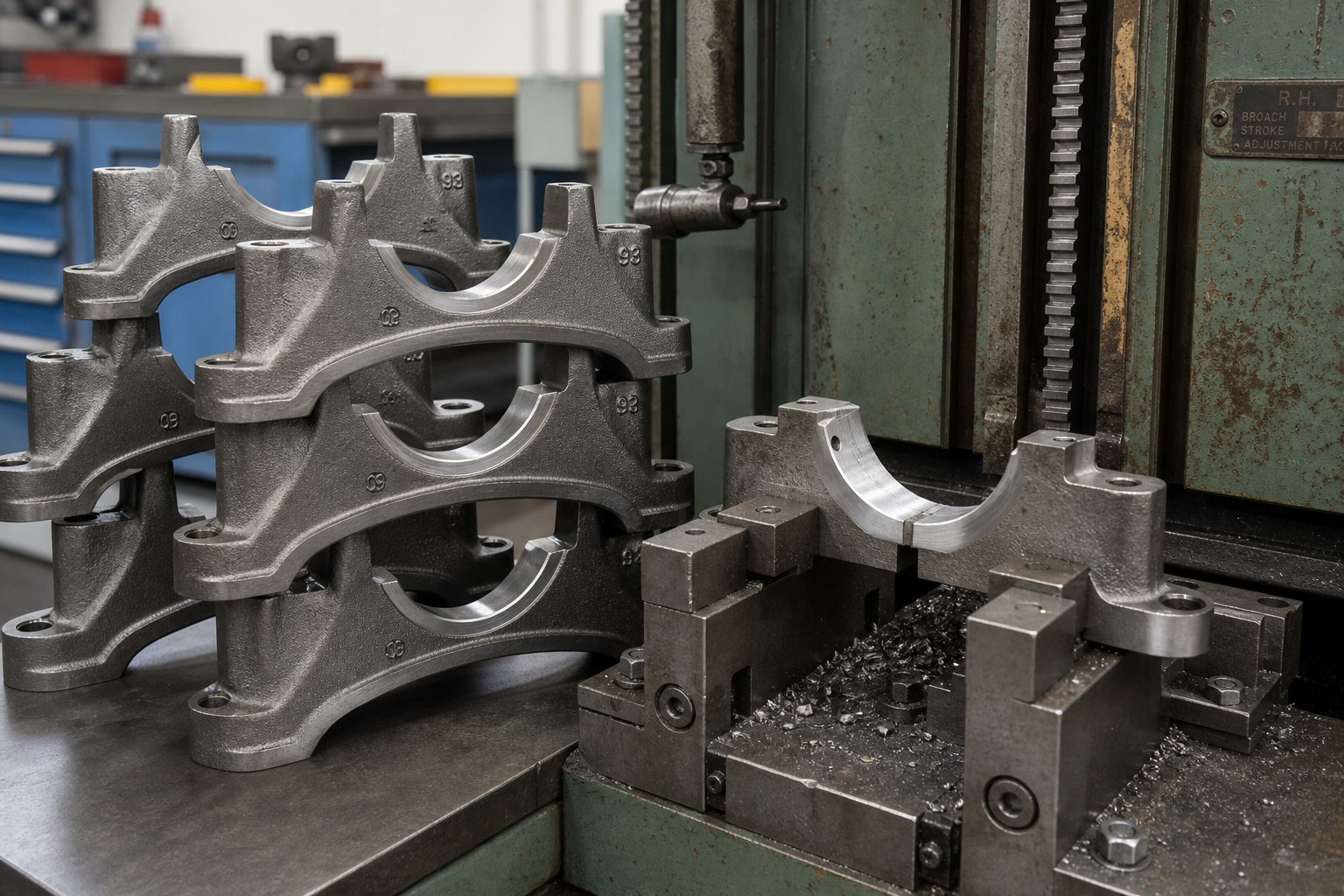
To avoid broach breakage, identify the cutting method before changing the setup. A long, progressively toothed broach, a CNC reciprocating insert and a rotary broach have different loading and clearance requirements. The useful question is where the tool stopped cutting normally: at entry, during engagement, at the end of travel or during withdrawal.
Table of Contents
- How to Avoid Broach Breakage: Start with the Cutting Method
- Check Broach Alignment Before Changing Cutting Conditions
- Match Broach Chip Clearance to the Actual Cut
- Separate Tool Wear from Holder Problems
- Assess a Damaged Broach Before Returning It to Service
- Review Tooth Geometry and Broach Regrinding History
- Keep Broach Damage Records Useful Across Production Runs
- Prepare a Focused Application Review
- References
How to Avoid Broach Breakage: Start with the Cutting Method
Pearson's machining textbook describes conventional keyseat broaches as stepped cutters: successive teeth remove a defined amount of material as the tool passes through the part. Its illustrated multiple-pass arrangement uses a matching guide bushing and shims. A shim changes the position of the tool for a later pass; it is part of a specified tooling combination, rather than an arbitrary way to increase removal.
CNC insert broaching uses a different control scheme. CNC Broach Tools discusses radial depth per pass, axial travel and clearance before radial retraction. In that arrangement, the program is directly involved in determining engagement and withdrawal. Advice about changing a programmed depth of cut therefore needs that process context.
Record which arrangement is installed before comparing troubleshooting advice. Include whether the feature is through or blind, whether the tool is pushed or pulled and whether a holder rotates. An instruction that mentions spindle speed or holder bearings belongs to a different setup from a long stationary keyway broach passing through a guide.
For the relationship between passes and stock removal, see the separate guide to multi-pass broaching. Keep the tooling supplier's drawing and operating instructions beside the setup record so that changes can be compared with the approved arrangement.
Check Broach Alignment Before Changing Cutting Conditions
In its push-broaching discussion, Pearson identifies alignment and lubrication as central operating concerns. A worn or loose press ram can make the broach dig in or break. The illustrated process also calls for cleaning the tool between passes and selecting a bushing that fits both the bore and broach.
These details make the guide and ram worth inspecting before treating every failure as a cutting-speed problem. A tool that enters at an angle should not be forced farther simply because the press has spare capacity. Check the documented tooling combination, seating surfaces and support arrangement against the setup that previously produced acceptable parts.
For a production review, distinguish the condition found from the proposed remedy. “Bushing was loose in the bore” is an observation; “fit a new guide” is an action that still requires the correct specification. Photograph the seating condition before dismantling it, and retain the rejected part with its entry and exit identified.
A useful setup record should connect the actual tool to its workpiece. A part number alone can conceal a changed pre-hole operation, a different material condition or a revised fixture. Record the drawing revision and the operation immediately preceding broaching so that the review includes the surface that guides the tool into the cut.
Match Broach Chip Clearance to the Actual Cut
CNC Broach Tools explains that chips can pack at the bottom of a blind keyway when there is insufficient relief. It also describes a cross-hole problem: a curved opposing wall can trap chips when the opening does not provide the necessary clearance. The resulting buildup can damage the insert or dislodge it from its pocket.
This is a geometric problem to review against the programmed path and finished feature. A bore that passes through a component does not automatically make the broached slot a through feature. In a bar-fed application, the material beyond the slot remains present until the part is separated.
When presenting a blind-feature problem for review, show a section through the actual relief and the tool envelope at maximum engagement. Include the direction of cutting and the withdrawal sequence. That drawing communicates more than describing the hole simply as “open” or “deep.”
For traditional push-keyway work, follow the specified cleaning and lubrication sequence rather than borrowing a CNC insert program change. For a related discussion of feature access, see blind keyway broaching.
Separate Tool Wear from Holder Problems
Slater Tools' rotary-broaching troubleshooting page lists an off-center holder, failing holder bearings and chip accumulation among the possible causes of machine alarming or stalling. Its holder check looks for free spindle movement; hesitation or a grainy feel calls for bearing attention under the supplier's instructions.
That distinction matters when a replacement cutting tool appears to encounter the same problem. Replacing the broach does not address a holder condition. Conversely, a holder diagnosis should not be applied to a conventional tool arrangement that has no rotary-broaching holder.
Slater's separate punch-broaching guide connects chipping and poor tool life with workpiece preparation, excessive removal per pass and material hardness. It specifies a 45 degree lead-in chamfer for that punch-broaching geometry. Treat this as an example of a preparation requirement tied to a particular tool system, rather than a universal chamfer for every broach.
Compare observations under separate headings: cutting edge, holder, workpiece preparation and programmed or mechanical motion. This avoids recording the broad label “broken tool” as if it were already a cause. For ongoing inspection planning, use the dedicated broach tool life guide.
Assess a Damaged Broach Before Returning It to Service
A worn cutting edge, a chipped tooth and a fractured body are different conditions. Describe the location and appearance of the damage before discussing repair. Include whether the damage reaches a locating or clamping feature and whether the tool's geometry remains measurable against its drawing.
The application review should ask the toolmaker or qualified reconditioning provider to define the proposed work and the acceptance checks. A price for sharpening alone does not answer whether a damaged body or holding feature is serviceable. Likewise, a visually smooth repaired area does not establish that the tool has recovered its specified geometry or material condition.
Keep the release decision separate from the initial visual inspection. Record who evaluated the tool, what work was performed, which drawing revision was used and what inspection result supports its return. If those details are unavailable, the assessment remains open.
Review Tooth Geometry and Broach Regrinding History
Carpenter Technology's specialty-alloy machining guide explains that a conventional broach incorporates feed and cutting depth through the steps between teeth. Its broaching chapter links the tooth radius to strength and chip-pocket space, and describes side relief, spline clearance and chip breakers as application-dependent design features. This makes a regrind history relevant to a failure investigation: the tool is a sequence of cutting geometries, not simply a sharp bar.
For its stainless-steel broaching applications, Carpenter recommends dedicated broach-grinding equipment or return to the manufacturer when the tool becomes dull. It also warns that edge nicks can score the work. Its troubleshooting chart connects improper grinding with chip packing and broken teeth, and notes that contamination beneath inserts can disturb their alignment.
For an engineering review, request a marked drawing that identifies the damaged tooth or insert and its position in the cutting sequence. Ask the reconditioning provider which dimensions were inspected and which surfaces were ground. A service record that says only “sharpened” leaves those questions unanswered. Keep that record with the tool rather than treating each return from service as an unrelated new item.
A practical comparison sheet
Use the following worksheet to organize measurements; the entries describe what to compare, rather than acceptance limits:
| Tool or setup item | Comparison to request | Question the comparison should answer |
|---|---|---|
| Damaged cutting section | Marked location against the tool drawing | Is the affected region roughing, sizing or another specified feature? |
| Reground surfaces | Service report against the drawing revision | Which dimensions changed during the last service? |
| Insert seating surfaces | Cleaned seat and installed position | Was the observed position measured before or after contamination was removed? |
| Guide and support | Installed arrangement against setup drawing | Does the inspected assembly match the approved assembly? |
| Rejected profile | Entry and exit identified on the part | Where should the toolmaker concentrate the dimensional review? |
Keep observations in the same coordinate system. “Left side of the tool” becomes ambiguous when a tool is turned over on a bench. A drawing view, cutting direction and marked tooth position make a photograph usable by someone who did not witness the event. Include a scale in damage photographs and keep the original image as well as any annotated copy.
Distinguish a proposed cause from a confirmed finding
Consider an illustrative investigation in which damage is found near the end of a cut. The useful starting record is the location, the tool arrangement and the last completed machine motion. Writing “excessive feed” immediately skips the evidence needed to assess that explanation. The reviewer still needs to know which feed or tooth geometry is being discussed and whether the recorded motion corresponds to the installed process.
Build a short hypothesis list beside the evidence. For each proposed cause, specify the measurement or inspection needed to assess it, the person responsible and the outcome. If a measurement cannot be recovered after dismantling, label it unavailable. Do not reconstruct a numerical result from an operator's impression of how hard the machine was working.
This approach also helps when several changes happened together. A replacement tool, a newly serviced guide and a different workpiece batch should each appear on the timeline. “The tool was changed recently” is too broad to distinguish a new tool from a reground tool or a tool transferred from another application.
Plan the review before changing the setup
As an application-review workflow, separate the problem description, proposed intervention and release criteria. The problem description should state what was observed and where. The intervention should identify the exact tool, fixture, program or material condition being changed. The release criteria should name the drawing requirements and inspection records that the responsible engineering team will use.
For example, a proposed guide replacement needs the replacement identification and the dimensions to be checked after installation. A program revision needs the old and proposed revision references and the feature being reviewed. A tool-service proposal needs the provider's scope of work and the agreed inspection deliverable. These records make the eventual decision reviewable without inventing a universal tolerance or machine setting.
When the setup is ready for an authorized trial, retain the approved trial plan alongside the results. Record the actual configuration used rather than copying the intended configuration from the request. If the trial differs from the approved plan, resolve the difference before treating its results as evidence for the proposed change.
Keep Broach Damage Records Useful Across Production Runs
Carpenter's warning about nicks and scored work provides a specific reason to connect tool condition with part inspection. A useful record should allow the reviewer to move from the affected part to the tool that produced it, and from that tool to its most recent inspection and service information.
The following is an editorial record format for that purpose. Assign the event a reference and link the machine log, rejected-part identification, tool identification and photographs to it. State which information was observed directly and which came from an operator's account. Preserve both; they answer different questions and should not be silently merged.
Close the event with the decision actually made. If the tool is retained for professional assessment, record who holds it and what evaluation is pending. If it is replaced, retain the failed tool's identity in the event record rather than overwriting the entry with the replacement number. If a component is scrapped, preserve the available inspection evidence before disposal under the site's own procedures.
A later recurrence can then be compared with a defined earlier event: the same cutting section, a different location, a different prepared hole or a different service state. This creates a useful basis for an engineering discussion while leaving the cause open until the relevant inspections have been completed.
Prepare a Focused Application Review
Pearson's matching-bushing procedure illustrates why tooling identification belongs in a troubleshooting request. Send the broach identification together with the guide or holder identification, workpiece drawing and the stage at which the abnormal event occurred.
Organize the request around the evidence available:
- The failed tool and the last acceptable part, clearly identified.
- The workpiece material specification and any measured hardness record.
- The pre-hole or prepared surface dimensions and inspection method.
- The setup drawing, support arrangement and actual cutting travel.
- The recent change that preceded the failure, if one is known.
These items form an application-review package, not a claim that a particular cause has already been proven. Ask the reviewer to identify the unresolved measurement before approving a process change. If the issue concerns machine suitability or an integrated broaching setup, contact UBright Solutions with the application details and available inspection records.
References
- Hand Tools: Arbor and Shop Presses — Pearson — Supports the conventional push-keyseat broach, guide, shim, alignment and lubrication discussion.
- Troubleshooting CNC Broaching: Tips and Tricks for Success — CNC Broach Tools — Supports the CNC insert-broaching discussion of blind slots, chip relief and withdrawal.
- Troubleshooting Solutions — Slater Tools — Supports the rotary holder and bearing diagnosis.
- Troubleshooting – Punch Broaching — Slater Tools — Supports the punch-broaching preparation and chipping discussion.
- Guide to Machining Carpenter Specialty Alloys — Carpenter Technology — Supports the stainless-alloy broach geometry, grinding and damage discussion; printed pages 77–81.